


Design of ultrasonic obstacle avoidance car based on single chip microcomputer
This paper completed the design of ultrasonic obstacle avoidance car based on MCU STC89C52. The program is written by KEIL development tool. The core components of the hardware part are ultrasonic sensor and motor driving module. When the car moves forward, the ultrasonic sensor sends pulses to detect the distance between the car and the obstacle. When the microcontroller detects the obstacle in front of the dangerous distance, that is, it is lower than the set safe distance, the alarm device sends an alarm signal, and at the same time, according to the pre-set rules and the specific position information of the obstacle, the output PWM wave controls the motor rotation and speed regulation, controls the car's turning and retreating, and completes the automatic obstacle avoidance.
With the continuous development of society, the progress of science and technology and the increase of labor costs, innovative, technological and even traditional enterprises have begun to focus on the development of intelligent cars, intelligent robots and other intelligent equipment. Jingdong has developed a smart logistics base, intelligent robot sorting express, intelligent car delivery to the designated location; Suning developed unmanned heavy trucks to support logistics distribution; Amazon develops smart warehousing; Ali to establish the smart One warehouse, intelligent car and intelligent robot will become the most important member of automated logistics, will complete a lot of work. Enterprises are also more and more high requirements for automation technology, intelligent obstacle avoidance is the first step of intelligent car autonomous work, therefore, the study of intelligent car obstacle avoidance technology for improving the function of intelligent car is crucial.
Automatic obstacle avoidance car its technical content covers the computer, mechanical and electrical, automatic control and sensor technology and other disciplines of knowledge field, the design of automatic obstacle avoidance car for automation major undergraduate graduates has a certain practical value, conducive to students to apply the knowledge to practice. This design combines the previous research results, the use of single-chip microcomputer technology, design intelligent obstacle avoidance car model, and finally complete the automatic obstacle avoidance car.
1 Overall design of obstacle avoidance car
The design of the car's core device is STC89C52 microcontroller, the car driving condition by the microcontroller control output signal, through the drive module output PWM wave control motor rotation, speed regulation. The functional core of intelligent obstacle avoidance car design lies in the realization of obstacle avoidance function of intelligent car. The key point of design is to solve the communication problem between the single chip microcomputer and the ultrasonic module. The ultrasonic module is mainly responsible for measuring the surrounding environmental data, while the single chip microcomputer is responsible for processing and judging the feedback information of the ultrasonic module. Through the motor drive module control car turning, backward and other obstacle avoidance function.
Ultrasonic intelligent obstacle avoidance car basic skills for the car can advance and autonomous obstacle avoidance. Motor L298N drive module plays a vital role in this respect. It is because of it, can be more convenient to drive the motor. Dc motor drives the wheels to realize dual drive driving. In the back of the car, equipped with tens of thousands of wheels can better cooperate with dual drive driving.
2. Hardware design of obstacle avoidance car
2.1 Microcontroller minimum system
This design uses 51 series of STC89C52 microcontroller. This kind of microcontroller is mainly optimized and upgraded on the basis of 8051 kernel. It is compatible with all the functions of 8051. Compared with 8051, its running speed is fast. The operating voltage of STC89C52 is 3.3-5.5V and the operating frequency is not higher than 40MHZ.
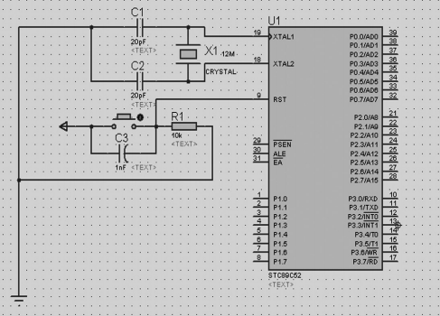
Figure 2 Microcontroller minimum system diagram
STC89C52 has 32 general I/O ports. Different ports have different structures and functions. Most of them can not only write but also output, as shown in Figure 2. P0 port because there is no internal pull-up resistance, when P0 is extended as the headquarters, it can be used directly without adding external components; When used as an IO port, an external pull-up resistor is required. In addition, the MCU has EEPROM and watchdog functions, 512 bytes of RAM, 8K bytes of FLASH, full duplex serial port, 3 16-bit timer/counter.
STC89C52 has two kinds of interrupt: timer interrupt and external interrupt. Timer interrupt means that the system interrupts when the time reaches the set time. When the external input signal has a falling edge, the external interrupt will occur; When the external circuit is a low level circuit, the external interrupt occurs later. The low level circuit can also allow the MCU to recover from the power failure mode.
The part of the circuit connected with the RST pin of the single chip microcomputer is the reset circuit, because the high level of the RST pin of the single chip microcomputer for 2us can be realized. Reset circuit is the MCU RST through the capacitor VCC, grounding through the resistance, the capacitor can be parallel button. When the user clicks the switch button, the VCC, capacitor and switch form a circuit, resulting in a short circuit to charge the capacitor, and the RST pin of the single chip microcomputer gets a high level, thus achieving the purpose of manual reset.
In Figure 2, the circuit formed by the wire connecting XTAL1, XTAL2 and GND is the clock circuit, and XTAL is the external crystal oscillator. The clock circuit consists of a crystal oscillator and two 20pF capacitors. The crystal frequency is 12MHz, which is the most common one, for the convenience of setting the baud rate.
2.2 Ultrasonic Module
This design uses ultrasonic sensor to avoid obstacles, ultrasonic ranging has the advantages of convenient, simple calculation, easy to realize real-time control, and in the measurement distance, measurement accuracy and other aspects can meet the requirements of actual use.
Ultrasonic module HC-SR04 is adopted, which is composed of ultrasonic transmitter, receiver and control circuit. The maximum range is 4m, the minimum range is 2cm, and the ranging accuracy is up to 3mm. The module has stable performance, accurate measurement distance, high precision and small blind area. It is usually used for robot obstacle avoidance, object ranging, public security and parking lot detection and other projects.
The ultrasonic module HC-SR04 is shown in Figure 3. It has four pins, including trigger signal Trig, Echo signal, power supply VCC and GND, and the measurement cycle is above 60ms. When Trig receives pulses of more than 10us, eight 40kHZ levels inside HC-SR04 are detected and echoes are detected.
When Echo just receives Echo, set 1(the received signal beyond a certain range is not enough for HC-SR04 to set 1 timer does not count), the MCU timer starts to calculate the number of times, until Echo does not receive signal, set 0, and record TH+TL machine cycle. A machine cycle requires 12 oscillating cycles, so the time can be calculated. Multiply the time times the speed of sound to get the distance S.
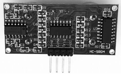
Figure 3 HC-SR04 Ultrasonic module
2.3 Motor drive module
This design uses the L298N motor drive module, which controls two DC motors to complete the car obstacle avoidance driving. The L298N motor drive module can drive not only two-channel DC motor, but also two-phase four-wire stepper motor, four-phase five-wire stepper motor and four-phase six-wire stepper motor. If two power supplies are used, the single chip microcomputer and L298N module are common, so that L298N can work normally and enable the motor. After the motor is powered, it is followed by the control of four signals IN1, IN2, IN3, IN4 input control motor braking, speed change, etc. If PWM Modulation is carried out on the DC motor, PWM (Pulse Width Modulation) pulse should be output on the enabling end, and the modulation can be realized.
The L298N has four inputs and four outputs. The input port is connected to P0, IN1 and IN3 of the single chip microcomputer for high power level, and the left and right motor is turning positive. The speed of the car is adjusted according to the duty ratio of PWM signal input by ENA and ENB port. When the right side of the car meets an obstacle, the car is controlled to turn left, the left motor stops, and the right motor rotates in variable speed under PWM signal modulation. When the car meets obstacles on the left side, control the car to turn right, the motor on the right side stops, and the motor on the left side rotates in variable speed under PWM signal modulation. When there are obstacles on the left and right, IN2 and IN4 ports are used to input the high level, IN1 and IN3 ports are used to input the low level to control the back of the car, and then the next operation, such as left or right turn, is performed.
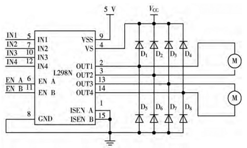
FIG. 4 L298N motor drive module
3 Obstacle avoidance car software design
3.1 Ultrasonic ranging program design
The ultrasonic ranging procedure flow is shown in Figure 5. Ultrasonic ranging program, the program code is as follows: defined a send_wave() function, to HC-SR04 Trig high level 10uS time, make the ultrasonic module emit ultrasonic wave, then reset the timer, start the timer, after receiving the returned sound wave, turn off the timer, through the timer time to calculate the distance, to achieve ultrasonic ranging.
3.2 Main program design
After the car starts, the ultrasonic module works, calls the ultrasonic ranging function, gets the distance, transmits it to the MCU, and then the digital tube displays the distance to the user. The system then calls the processing display function to judge whether it is less than the set safety distance. If it is less than the safety distance, the sound and light alarm is called to the alarm function and the car escape subroutine. Control drive circuit, the car in accordance with the predetermined obstacle avoidance rules travel obstacle avoidance. That is, when the right side of the car meets an obstacle, the car is controlled to turn left, the left motor stops, and the right motor rotates in variable speed under PWM signal modulation. When the car meets obstacles on the left side, control the car to turn right, the motor on the right side stops, and the motor on the left side rotates in variable speed under PWM signal modulation. When there are obstacles on the left and right, IN2 and IN4 ports are used to input the high level, IN1 and IN3 ports are used to input the low level to control the back of the car, and then the next operation, such as left or right turn, is performed. If not, continue to use the trolley advance function and continue to measure the distance.
4 Conclusion
In this paper, an ultrasonic obstacle avoidance car based on STC89C52 microcontroller is designed, which uses HC-SR04 ultrasonic module and L298N motor drive module. The ultrasonic sensor detects the distance between the car and the obstacle, and the single chip computer judges the position information of the obstacle. According to the pre-set rules and the current position information of the obstacle, the L298N motor module controls the motor forward, turn or back to achieve automatic obstacle avoidance.
This design has done some work in some parts, but the design is not perfect, still need to continue to improve, if the design into the actual application of the product also need to be constantly improved and improved.