


The invention relates to a security system based on ultrasonic wave and infrared ray
With the rapid development of science and technology today, people's pursuit of quality of life is constantly improving. The appearance of various high-tech products in recent years has brought people a lot of convenience. Although smart home is not an emerging technology, but because of the domestic industry standards are not unified, expensive, poor after-sales and many other factors [1], people are discouraged by the actual utilization rate of smart security is not high. The ultrasonic and infrared control technology proposed in this paper is simple in operation, convenient in use, reliable in operation and low in price, which is conducive to wide application.
1. Overall system design
As shown in Figure 1, the overall design structure of the system can be divided into single chip microcomputer main control module, sensor module and output driver module.
The sensor module is divided into ultrasonic sensor and infrared sensor. The single chip microcomputer is the main control chip, which sends the signal to the ultrasonic transmitter through the program to drive the output action when the ultrasonic and infrared sensor signals are received. The sound and light alarm adopts the on-site alarm mode. The remote wireless alarm is sent by the single chip microcomputer to the communication module, and then the communication module is connected to the security office to realize the remote rescue.
2 Hardware Design
The single-chip microcomputer is used as the main control module in the system. It has the advantages of low voltage, high performance, and is equipped with an independent reset button, which is convenient and flexible to use. The ranging signal of ultrasonic sensor and the positioning signal of infrared sensor are respectively input through the I/ O port. According to the software algorithm, the output end of sound and light alarm, LED display and wireless alarm are driven. This design through the setting of light flashing color and alarm sound to distinguish the distance and orientation of obstacles
2.1 Microcontroller minimum system
The minimum system of single-chip microcomputer is shown in Figure 2, including single-chip microcomputer, crystal oscillator circuit and reset circuit. The reset circuit connects a key switch S1 to the 10μF electrolytic capacitor C3 in parallel. When the switch is pressed, the capacitor discharge RST will be pulled to a high level, and the high level will remain when the capacitor is charged, so that the MCU can complete the reset. The internal clock of the single chip is provided by the crystal oscillator circuit. In this design, 12 kHz resonant capacitance C1 and 30 pF porcelain capacitors are selected for clock signal frequency to filter out the high-frequency signals of the crystal oscillator part and make the crystal oscillator work more stable [2].
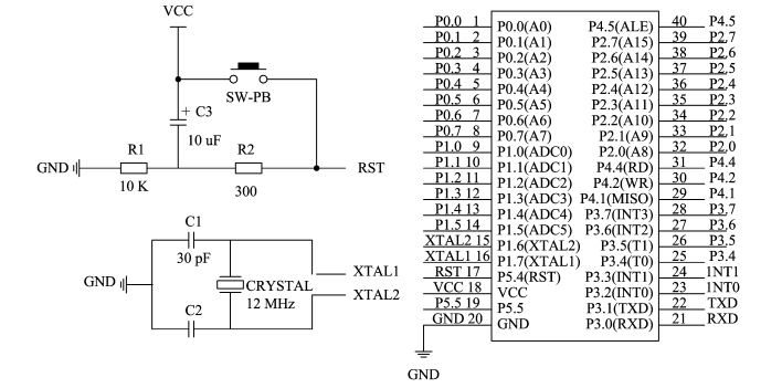
Figure 2 MCU minimum system
2.2 Ultrasonic Sensor
Principle of ultrasonic ranging technology is simple, convenient distance, but as a result of ultrasonic emission is serious, in the distance measurement error when ꎬ so not appropriate location. This design uses HC-SR04 ultrasonic module, its stable performance, accurate ranging, can be used for ranging within 300 cm.
The working principle of the ultrasonic sensor is shown in Figure 3: a pulse with a frequency of 40 kHz is sent out by the control circuit of the single chip microcomputer (at the same time, the counting circuit is started to time) and acts on the probe at the ultrasonic sending end. The inverse piezoelectric effect will occur on the probe, thus generating resonance and forming mechanical vibration wave, which is the ultrasonic wave that needs to be sent. When the ultrasonic wave meets obstacles, it is reflected back and received by the probe at the receiving end of the ultrasonic wave. Then it is converted into an electrical signal through the piezoelectric effect. The receiving circuit amplifies, detects and shapes the signal at multiple levels and then acts on the microcontroller of the microcontroller. According to the formula L = 1/2vt, the sound velocity t with the measured distance Lv of 340m/s is calculated as the time from the first transmitting pulse to receiving the echo.
The pyroelectric human infrared sensor uses SD02 for its detection principle
3 System workflow
The system working flow chart is shown in Figure 5 [4]. Before using the sensor module, reset all parameters. Then the system enters the control state. When someone enters the security area, the information detected by the infrared sensor is transmitted to the microcontroller, the microcontroller sends pulse signals to the ultrasonic transmitting probe, the timing starts, and the timing stops after receiving the ultrasonic wave reflected back by the obstacle. Single chip after a time delay,
4 Test
In order to verify the accuracy of the system and precision and compared with the single infrared sensor system test set up the experimental group and control group two experiments divided into five groups [5]. Test indoors open area preset system alarm interval is 50 ~ 000 mm 3 test time is 8:00 ~ 18:00 everyday. The actual distance between the intruder and the alarm is measured by measuring tape. The results are shown in Table 1Through comparing test results ꎬ the measurement error and omission of number of experimental group is lower than the control group, number of false positives slightly more than the control group. The reason is that the design system does not take into account the influence of interference sources similar to the human body, so there are false positives. Later, we should cooperate with image sensing to further reduce false positives.
5 Conclusion
In order to realize efficient data classification, a data logic analysis algorithm based on statistical analysis is proposed, and common machine learning data sets are used to verify the framework of this paper. The results show that this method can improve the accuracy of classification and reduce the calculation time. There are two main work to be done: one is to improve the real-time classification performance of the classification algorithm in this paper through further improvement and optimization; the other is to realize the algorithm in a real system and verify the real-time classification performance of the algorithm.
Take part in the essay
[1] Wang Zhiqiang, Wang Zhiqiang. Comparison of four discretization Methods Based on Entropy [J]. 2016-18(3):69.
[2] Wang Zhigang, Liu Zhigang. Minimal cutting method of functional zoning: A case study of Italy [J]. Optimization Letter 201610(5): 955-973.
[3] Wang Zhiqiang, Wang Zhiqiang, et al. Research on Tool Choice Behavior Based on Logical Analysis Data [J]. Computer and Operations Research 2019106:191-201.
[4] Wang Zhiqiang, Wang Zhiqiang, et al. A data mining method based on Machine Learning [J]. Expert System and Application 2019122:388-405.
[5] Wang Zhiqiang, Wang Zhiqiang. Research on the Optimization of Complex Model [J]. International Journal of Applied and Research Basic Science 20134(9): 2810-2816.
[6] polat kgunes s. Diagnosis of breast cancer Based on least squares support vector Machine [J]. Digital Signal Processing 200717(4): 694-701.
[7] Often Chunchun Lin Chunjiang. A Support vector library Based on svm [J]. Acm Journal of Intelligent Systems Technology (TIST)20112(3):27.