


Design of an airborne ultrasonic liquid level sensor
0 Introduction
The waste water treatment system is an indispensable part of civil aircraft, and the waste water storage tank is an important component of the treatment system. The liquid level detection plays a decisive role in the normal operation of the whole system. At present, the commonly used liquid level measurement means mainly include contact type and non-contact type. The contact type mainly includes manual measuring method, float measuring device, servo type, capacitance type and magnetostrictive type. The common characteristic of the contact type is that the induction element is in contact with the measured liquid, and there are risks such as wear and easy to be stuck by the liquid and corrosion. Non-contact type mainly includes microwave radar, ray, laser and ultrasonic level meter, whose common feature is that the induction element does not contact with the measured liquid and is not affected by the medium [1]. Compared with radar, ray and laser, ultrasonic liquid level gauge system is relatively simple, not susceptible to electromagnetic interference, easy to miniaturize, suitable for airborne application scenarios, and relatively low cost, conducive to civil promotion, and widely used in industrial production and scientific research. Therefore, the ultrasonic level meter is the first choice as the liquid level detection means of waste water storage tank.
The traditional ultrasonic liquid level gauge is usually installed at the top or bottom of the container to judge the liquid level by the echo reflected from the liquid and gas interface. Aircraft waste water storage tank is capsule shaped structure, the sound wave will be reflected for many times to produce reverberation, so that the noise becomes larger, affect the signal detection; In addition, the deposition of impurities in the waste water tank seriously affects the propagation efficiency of sound waves and also leads to the failure of liquid level detection. According to the investigation, the detection of liquid level by airborne waste water storage tank is fixed point judgment, that is, when the liquid level reaches a specific position, the detection system will alarm. In view of the above requirements, this paper designed a low power ultrasonic level sensor for fixed point detection. Based on the change of ultrasonic transmission efficiency, acoustic attenuation, resonant frequency and other parameters with the medium, the ultrasonic transducer pair placed inside the fully closed shell is used to judge the transmission medium between the transducer pair by detecting the change of the received signal amplitude. To achieve the purpose of distinguishing liquid and gas, and finally realize the fixed point detection of liquid level.
1 Theoretical Analysis
1.1 Transmission coefficient
When the plane acoustic wave is vertically incident from medium 1 to medium 2, the sound pressure transmission coefficient tp at the interface is
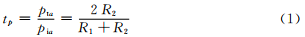
The sound intensity transmission coefficient ti is
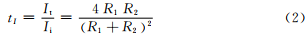
It can be seen from equations (1) and (2) that the impedance difference between the two sides of the dielectric interface will directly determine the transmission coefficient of sound pressure and sound intensity.
1.2 Sound attenuation
In practical engineering, acoustic wave attenuates when propagating in most materials, which can be expressed by power function [3] as

1.3 Resonant frequency
Considering the radiation impedance, the resonant frequency of the ultrasonic transducer [4] is
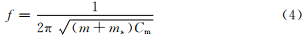
Where: m is the equivalent mass of the transducer; Cm for transducers, etc.; ms is the medium resonance mass.
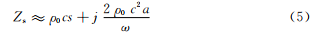
In order to distinguish the amplitudes of air and water, multiple frequency bands are selected for analysis. The planar piston emitter is used as the approximation of the current structure. When the high frequency radiation (a≥λ), its radiation impedance [4] is approximately
The radiated sound power is approximately
It can be seen from equations (4) ~ (6) that the medium has a significant influence on the radiation impedance and radiation sound power. When the medium is different, the resonant frequency of the structure will be offset and the radiation impedance will be offset accordingly. In the resonant state, its surface vibration velocity is the maximum in a specific frequency band, and its radiated sound power is also the maximum. In this case, the device can work in a low power consumption.
2 Sensor Design
2.1 Overall Design
The overall design of the sensor is shown in Figure 1. The main control chip sends out a pulse sequence of specific frequency, and sets a certain logic sequence to control the analog switch, so as to control the transmission and reception of the ultrasonic transducer. The analog switch amplifies the current of the received signal and compares the voltage. Then the main control chip collects the data and determines whether the liquid level is reached.
In order to improve the accuracy of monitoring, a dual judgment design is adopted. The two poles of the ultrasonic transducer are both the transmitting end and the receiving end. The two poles transmit ultrasonic signals at the same time, and analyze the received signals at the same time. When the judgment results of both ends are consistent, it is the final judgment result.
2.2 Structural design and finite element analysis
According to the theoretical analysis, the fixed-point monitoring of liquid waste water level can be realized by receiving signal amplitude. In this paper, a fully enclosed detection structure is designed (see Figure 2). The metal shell immersed in water is fully enclosed, and the part of the ultrasonic transducer is inside the shell and rigidly connected to the shell. The ultrasonic wave of the transmitting transducer passes through the metal shell in the medium, then passes through the shell, reaches the receiving transducer, and is converted into electrical signal. Through analysis and processing, it can be determined to be liquid or air, so as to realize the liquid level fixed point detection.
In order to verify the validity of the structure, the finite element analysis of the structure is carried out, and the axisymmetric finite element model of the structure is established. For simplicity, only the part of the shell connected with the transducer is analyzed, and the ultrasonic wave propagated directly by the metal shell is not considered, so the axisymmetric model is adopted. The main purpose of finite element analysis is to quantitatively compare the transmission effect of liquid and gas medium. Therefore, the model only includes PVC shell, aluminum shell and transmission medium. Displacement load is applied on one side of PVC, displacement is extracted at the center of the circle on the other side, and frequency response curve is drawn.
2.3 Selection of ultrasonic transducer
Frequency is an important parameter to be considered in the selection of ultrasonic transducer. Problems such as directivity of sound field and energy loss must be considered comprehensively to determine the working frequency of the transducer [5].
According to the actual application scenario, there may be many solid suspended impurities of different sizes in the liquid, so the larger the distance between ultrasonic waves, the better. But because of the sealing design, the ultrasonic wave through the 2mm aluminum shell spread out, there is a large attenuation, the transmission spacing needs to be as small as possible, the final selection of the transmission spacing of 20 mm. At the same time, considering the demand of miniaturization, three kinds of transducers with frequencies of 40kHz, 200kHz and 1MHz were initially selected to test the amplitude changes of their transmitted signals after passing through water and air respectively. The 40 kHz transducer is based on the piezoelectric ceramic bending vibration, and the 200kHz and 1MHz transducer is based on the thickness vibration. The test results are shown in Table 2.
The amplitude of 40kHz signal in water is much lower than that in air. This is because the transducer's driving structure makes its vibration displacement decrease or not vibrate in water with high resistance. Therefore, this transducer model is excluded. The amplitude of 200kHz signal is very low in both water and air, because its internal structure affects the transmission efficiency. The transducer is also not suitable for the scenario in this paper. The amplitude of 1 MHz signal in water is much higher than that in air, so 1 MHz is chosen as the detection frequency.
The commonly used methods to analyze the amplitude-frequency characteristics of received signals include point frequency method and sweep frequency method. If the dot frequency signal is used, the different medium conditions will lead to different reception matching, resulting in a large fluctuation of signal amplitude at the receiving end, and it is difficult to correctly judge whether there is medium in the middle of the level gauge through the amplitude. When the frequency sweep signal is used, the obstacles of different sizes can be effectively avoided under different frequency conditions, and under different density medium conditions, according to different frequency matching conditions, the impedance matching of ultrasonic transducer can reach the best state, so that the amplitude of the received signal can be maintained at a stable value, and accurate monitoring can be achieved.
Therefore, the scanning signal with 1MHz as the center frequency is used as the excitation signal of the ultrasonic transducer in this paper.
2.4 Hardware circuit design
The circuit of the monitoring system uses C8051F series main control chip to generate 1 MHz sweep square wave. The square wave signal is processed by the amplifier and the follower, and the impedance is matched to the ultrasonic transducer, and then the transducer outputs the acoustic signal of the corresponding frequency. At the same time, the signal received by the transducer passes through the voltage comparator and is sent to the main control chip for judgment, so as to realize the accurate judgment of whether the liquid level is reached.
The hardware circuit can be divided into four parts:
1) Transmitting circuit: used to stimulate the ultrasonic transducer signal, so that the ultrasonic signal of a specific frequency.
2) Time-sharing multiplexing circuit: It is used to realize the accuracy of detection and meet the fault self-detection function, which is realized by using multi-channel analog switch.
3) Receiving circuit and signal demodulation circuit: used to amplify and process the received signals, demodulate the amplified signals and send them to the main control chip for processing. Because the whole sensor is weak signal detection, so before demodulation, the signal should be carried out three processing: current amplification - voltage amplification - low voltage filtering.
4) Alarm and failure detection circuit: Because in practical application, many solid-liquid mixtures detected are inflammable and explosive dangerous goods, it is necessary to isolate the external power supply from the internal power supply. When the liquid level reaches or the system fails, the main control chip sends out a control signal, and the optocoupler outputs a high level. At this time, the internal voltage is low and the external voltage is high, meeting the actual application requirements.
3. Top-level algorithm design
In the overall design, two ultrasonic transducers A and B are used in order to realize the accurate judgment of whether the liquid level is reached. First, A transmits and B receives, interpreting whether the signal received by B is in the air or in the solid-liquid mixture; Then B transmits and A receives, and determines whether the signal received by A is in the air or in the solid-liquid mixture. The common results of the two are used for comprehensive judgment. The flowchart of the specific design idea is shown in Figure 5.
The main control chip (MCU) generates 1 MHz sweeping square wave, which is transmitted by transducer A and received by transducer B through the control of analog switch. The received signals enter MCU, are judged by amplitude and recorded as B0 and B1 corresponding to different states respectively. Then, by controlling the analog switch, the transmitter is switched to the transducer B, and the transducer A is received. The received signal enters the MCU, which is judged by the amplitude and recorded as A0 and A1 corresponding to different states respectively. The final comprehensive judgment is made. If the result is A1 and B1, the liquid level is judged to have reached. If the value is A0 and B0, the liquid level is not reached. Others are judged to be faulty.
4. Experimental results and data analysis
In order to verify the effectiveness of the sensor, dot frequency and sweep frequency are used to test the sensor. As the liquid density in the aircraft waste water tank changes greatly, the acoustic wave transmission medium is considered as air, water, sewage with more suspended impurities. The signal wave shape of the sweep signal reaching the receiver after transmission through three media is shown in Figure1
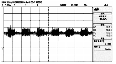
Figure 1 Signal waveform of the sweep signal reaching the receiving pole through the air
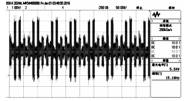
FIG. 2 Signal waveform of the sweep signal reaching the receiving pole through clean water
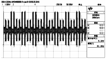
FIG.3 Signal waveform of frequency sweep signal reaching the receiving pole after passing through sewage
As can be seen from Figure 6-8, the signal amplitude after air transmission is significantly lower than that after water and sewage transmission, and the received signal amplitude is similar in the case of water and sewage, which indicates that the difference of liquid density and turbidity has little influence on the received signal amplitude. The sensor can accurately and stably distinguish between air and liquid without misjudgment due to liquid difference.
5 Closing Remarks
Based on the basic characteristics of ultrasonic wave, a reasonable and effective closed detection structure is designed by finite element analysis. The swept signal is used as the excitation signal, and a double judgment algorithm is designed to analyze the received signal, so as to distinguish whether the ultrasonic transmission medium is air or liquid. The test results show that the ultrasonic liquid level sensor designed in this paper can accurately and stably monitor the liquid level in the aircraft waste water tank, and effectively realize the fixed-point liquid level alarm function.
References:
[1] Dong Dijing. Development of Ultrasonic Liquid Level Sensor [D]. Tianjin: Tianjin University, 2008. (in Chinese)
[2] Du Gonghuan, Zhu Zhemin, Gong Xiufen. Fundamentals of Acoustics [M]. Edition 3. Nanjing: Nanjing University Press, 2012.
[3] Li Ji, Li Li, Deng Yonggang. Study on Frequency Domain Sound Field of Air-coupled Ultrasonic Transducer [J]. Journal of mechanical engineering, 2019 zhongguo kuangye daxue (10) : 10 16.
[4] He Zuoyong, Zhao Yufang. Theoretical basis of Acoustics [M]. Beijing: National Defense Industry Press, 1988.
[5] Zhao Junjie, Wang Yan, Zhang Xianyu. Discussion on the Selection of Piezoelectric Transducer for Liquid Level Gauge [J]. Automation & Instrumentation, 2013 (4)