


Method to eliminate the influence of ambient temperature on the performance of tilt sensor
In the 1990s, air flow inclination sensors were widely used. The air flow inclination sensor has the characteristics of gas mass, low inertia, shock resistance and short response time, and can be used in industrial attitude control system. However, almost all transducers suffer from the problem of temperature drift, that is, sensitivity and zero voltage drift with temperature. The sensitive medium of the inclination sensor is gas, and the sensitive element senses the temperature change of the flow field caused by the difference between the heat source inside the sensor and the ambient temperature. In order to solve the problem of temperature variation, the existing methods are compensated from both hardware and software aspects. However, the existing method is basically to compensate after drift according to the law of change, that is, to correct after drift. Based on the sensitive mechanism of the airflow inclination sensor, the similarity law of viscous fluid motion is adopted
In this paper, a compensation method using temperature compensation circuit to eliminate ambient temperature shadow noise is proposed and verified by experiment.
1. Sensitive mechanism of airflow inclination sensor
The principle of inclination Angle measurement by airflow inclination sensor is shown in Figure 1. The heat source and two heat elements are arranged in a horizontal cylindrical closed chamber. The lamp filament heat source is placed along the axis of the cavity, and the thermal filament is placed on both sides of the heat source to form two sensitive arms of the measuring bridge. When the sensor is placed horizontally, the two hot wires are located in the same temperature zone of the air flow field, the bridge is balanced, and the voltage output is zero. When the sensor is tilted, the hot wire above the horizontal plane is in a high temperature position, and the hot wire below the horizontal plane is in a low temperature position, causing the bridge to lose balance, the bridge has a potential difference output, and the voltage signal is proportional to the tilt Angle.
2 Detection circuit
Figure 2 shows the detection circuit of the airflow inclination sensor. R1 and R2 are the two hot wires, and R is the thin resistor, so that R = R1 + R2. Then the output of the bridge can be shown as
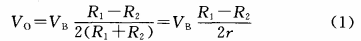
In the formula, VB is the supply voltage of the bridge circuit; Vo is the output voltage of the circuit. When the sensor is tilted, the resistance value of the two thermal wires must be that the resistance of one wire increases and the resistance of the other wire decreases, and the absolute pair of temperature changes can be considered equal. Therefore, the (R1+R2) basis is unchanged, and the output of the bridge is determined by (R1+R2).
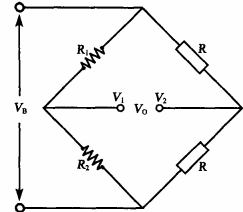
Figure 2 Bridge detection circuit
For the commonly used platinum resistance Pt100, there is a resistance value - temperature (R-T) relationship [4] :
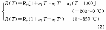
Where, is the resistance at a reference temperature of zero degrees Celsius; Generally domestic production of high purity platinum wire a1=0.003926. The nonlinear term in equation (2) is small, so it can be ignored, that is, only take

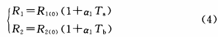
Ta and Tb represent R1 and R2 respectively. The temperature of the location. Since the two platinum wires have the same length, R1 (0) =R2 (0) =R (0) can be set, so the resistance difference between the two thermal wires can be written as

By substituting formula (5) into formula (1), the relationship between the bridge output voltage and the temperature difference between the two thermal wires can be obtained as
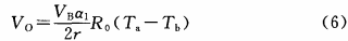
As can be seen from equation (6), the output voltage of the bridge is determined by the temperature difference between the two thermal conductors. If the ambient temperature is different, the temperature field will be completely different, so that the temperature difference between the two thermal wires will change, the output voltage of the bridge will be different, thus affecting the output of the sensor, resulting in error; If the temperature field is kept similar at different ambient temperatures, the temperature difference between the two thermal conductors will not change, and the output voltage of the bridge will not change, that is, the measurement of the inclination will not change with the change of the ambient temperature.
3 Compensation Mode
The temperature of the two thermal wires is determined by the temperature field formed by the heat source, so the temperature difference between the two thermal wires is also determined by the temperature field. When the ambient temperature changes, the temperature field also changes, and the output voltage of the bridge also changes. As can be seen from Figure 3, the ambient temperature dip Angle obtained by the -20 ~ +30℃ test is 30°. When the bridge output voltage. The test results show that the output voltage varies with the ambient temperature. When the ambient temperature increases, the difference between the ambient temperature and the heat source temperature decreases, and the output voltage decreases.
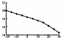
FIG. 3 Relation between the output voltage and the ambient temperature at an Angle of 30°
The temperature field is determined by the heat source inside the sensor and the ambient temperature. When the temperature difference between the heat source inside the sensor and the ambient temperature is unchanged, it can be seen from the flow similarity principle that when the temperature field is similar, the temperature difference between the two thermal conductors is basically unchanged, and the output voltage of the bridge will also be basically unchanged. It can be seen from the above tests that the variation of the bridge output voltage with the ambient temperature is due to the change in the temperature difference between the heat source inside the sensor and the ambient temperature. Therefore, the compensation circuit is designed to change the temperature of the heat source so that the temperature difference between the heat source and the ambient temperature remains unchanged and has an optimal value. This can improve the performance and application range of airflow inclination sensors. The design of the compensation circuit is to set the supply voltage of the heat source to constant voltage. A thermistor is connected in series on the power circuit of the heat source. The resistance value of a thermistor varies with the ambient temperature. Therefore, when the ambient temperature changes, the voltage at both ends of the heat source also changes, so that the temperature of the heat source can be changed. Through reasonable calculation and design, the purpose of reducing temperature drift can be achieved.
4 Test verification
The sensor tilt Angle is 30°, the heat source voltage V = 1.85V, and the bridge power supply voltage is 1.4V.
4.1 Relationship between bridge output voltage and ambient temperature
When the ambient temperature is measured in the range of -20 ° C to + 30 ° C, the bridge output voltage is shown in Table 1
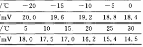
Table 1 The relationship between the bridge output voltage and the ambient temperature
As can be seen from Table 1, when the ambient temperature changes (the heat source temperature D is unchanged), the bridge output voltage will change. When the ambient temperature increases, the temperature field gradient decreases, the output signal of the bridge decreases, and the output signal of the bridge almost changes linearly with the ambient temperature.
4. 2 Measure the voltage adjustment value when the temperature of the heat source changes by 1℃
The ambient temperature and heat source voltage can be adjusted to obtain approximately the same output voltage signal. When the sensor inclination is other values, the regulation law of the heat source voltage is consistent with the above law.
4. 3 Test and verify
Under the conditions of ambient temperature 0, heat source voltage V= 1.85V and bridge output voltage, the tilt Angle of the sensor is measured by 10°, 30° and 45° respectively.
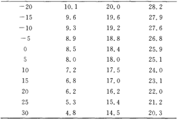
Table 2 Bridge output voltage when the heat source voltage is not adjusted
Adjust the heat source voltage and the input voltage data of the rear bridge are shown in Table 3. The heat source voltage is adjusted according to the ambient temperature according to the rule of equation (9). It can be seen from the data in the table that after the electric base of the heat source is adjusted according to the rule of Formula (9), the output voltage of the bridge is basically unchanged, and the law is consistent when the sensor inclination is 10°, 30° and 45° respectively.
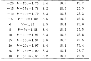
Table 3 The bridge output voltage after adjusting the heat source voltage
It can be seen from the test results under the tilt Angle of the three sensors verified by the above test that by changing the temperature of the heat source (here, by adjusting the voltage of the heat source) and keeping the difference between the heat source and the ambient temperature unchanged, the output voltage of the bridge can be basically unchanged.
The test data show that the difference between the heat source and the ambient temperature remains unchanged by adjusting the heat source temperature, that is, the temperature field remains similar. The output voltage of the bridge is basically unchanged, that is, it does not change with the ambient temperature, and the influence of the ambient temperature change on the airflow inclination sensor is eliminated.
5 Conclusions
(1) By changing the temperature of the heat source inside the sensor, the temperature difference between the heat source and the ambient temperature is kept constant, so that the output voltage of the bridge is basically unchanged.
(2) The temperature compensation circuit can effectively eliminate the influence of ambient temperature on the airflow inclination sensor.
Reference article:
[1] Lin Yu. Research on Principle, Structure and Performance of air pendulum attitude sensor [D]. Beijing: Beijing Institute of Electronic Science, 2005.
[2] Zhang Fuxue. Study on oscillating characteristics of air flow in closed chamber [j]. Acta Electronica Sinica, 1999,27(1):1 4-1 1 4 2.
[3] Zhang Fuxue. Natural convection gas pendulum characteristics and its application in EJ3 sensor Engineering Science, 2002,4(8):50-53.
[4] Pan Wencheng. A high precision platinum resistance temperature measurement method. Sensor Technology, 2003,22 (11): 69-71
[5] Hu Wenxu. Research on precision temperature measurement of platinum resistance [J]. Journal of Shaanxi Normal University (Natural Science Edition), 2000,28(4):59-62.