


Design of ultrasonic sensor array number automatic detection system
0 Introduction
With the rapid development of modern society information, automatic identification of the number of people in public places has very important practical value and broad prospects in the fields of traffic, commerce, public safety and so on. By counting the number of people in a certain area, resources can be easily allocated and scheduled to achieve efficient use of resources. For example, the detection of the number of people waiting outside the elevator of a high-rise building can change the scheduling strategy of the elevator according to the difference between the number of people waiting and the time. To count the number of people waiting for buses at public transport stops, adjust the number of working vehicles and monitor the traffic situation. Count the number of people on public vehicles and other means of transport, and detect the number of people entering and leaving fixed areas.
At present, the crowd size detection system mainly includes: the number of people detection system using the principle of image recognition, the number of people detection system using infrared sensor, the number of people detection system using photoelectric switch detection. The number of people detection system of image recognition selects a large number of pictures containing human features, uses the image processing separator to analyze the samples, and detects the number of people in the image of a fixed area. The infrared human body sensor detection system is obviously affected by the ambient shadow noise, and the error is large. Due to the limitation of overlapping population and small detection area, the detection error of photoelectric switch detection system is also large.
Ultrasonic propagation in the air is not easy to be disturbed by the surrounding environment, and the attenuation speed is slow, the propagation distance is long, and it has the advantages of easy realization, low cost, good reliability and so on. At present, ultrasonic sensor arrays are widely used in obstacle positioning, vehicle collision avoidance system and robot obstacle avoidance system.
These systems do not have the function of measuring the number of people, and their structure, measurement principle and installation method are different from this system.
1 Overall system design
Ultrasonic sensor array automatic detection system is based on the principle of ultrasonic distance measurement.
The system is mainly composed of microprocessor, power module, output communication interface module, output digital interface module, keyboard module, display driver module, display module, ultrasonic signal amplifier circuit module, ultrasonic transmitting array, ultrasonic receiving array, ultrasonic signal receiving and switching array, ultrasonic receiving signal processing circuit array, etc.
2 System working principles
The ultrasonic transmitting array group and the ultrasonic receiving array group are installed in the area above the crowd, and the distance between the ultrasonic transmitting array group and the ultrasonic receiving array group and the support plane of the area where the crowd is located is 2 ~ 5m. The area above the crowd is divided into hexagons according to the honeycomb. The center of the hexagonal area is installed with the ultrasonic transmitter and the ultrasonic receiver, and the spacing between the two ultrasonic transmitters and the two ultrasonic receivers is 200 ~ 400nlm. Select the ultrasonic sensor with small divergence Angle. The higher the sensor is from the ground, the more it is necessary to extend the distance between the sensors and devices.
The significance of the division of honeycomb hexagon is shown in Figure 2. In Figure 2, each hexagon is numbered in order of arrangement. The ultrasonic sensor array is divided into four groups according to the row number: odd row and odd row group, even row and even row group, odd row and odd row group. The system uses 40kh, 50kh, 60kh or 70kh ultrasonic receivers and transmitters.
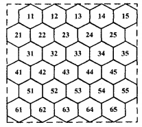
FIG. 2 Schematic diagram of ultrasonic sensor division
When the system is working, ultrasonic voltage signal is generated by the microprocessor unit, and the duration of ultrasonic voltage signal is 1 pheasant. The ultrasonic drive voltage signal is amplified by the ultrasonic signal amplifier circuit module, and then the ultrasonic emission array is driven. The ultrasonic transmitting array installed above sends out ultrasonic signals, and the ultrasonic sensor adopts the detection mode of direct reflection. Ultrasonic waves travel through the air, encounter the ground or people on the ground, and the ultrasonic waves will be reflected. The reflected ultrasonic waves are received by an array of ultrasonic receivers and converted into electrical signals. The electrical signals sent by each ultrasonic receiver in different ultrasonic receiver arrays are selected by the ultrasonic switching circuit and sent to the ultrasonic receiving signal processing module for signal processing. The processed ultrasonic electrical signal is transmitted to the microprocessor unit, which automatically measures the ultrasonic wave from the ultrasonic transmitter, so that the ultrasonic wave is reflected and received by the ultrasonic receiver. The software calculates the distance between an ultrasonic transmitter and an ultrasonic receiver and the ground or a person under the ultrasonic transmitter and ultrasonic receiver.
Before the system is officially operational, it is necessary to save the measured distance in the case of empty ground. If the distance measured during the operation of the system is less than the saved distance and exceeds the set range, it is judged that there is someone under the ultrasonic transmitter and ultrasonic receiver. According to the measured distance between each set of ultrasonic transmitters and ultrasonic receivers, determine whether there are people below it, and then add up the number of people under all ultrasonic transmitters and ultrasonic receivers. This number is multiplied by a population concentration factor to get the total number of people in the area. The combined coefficient of the number of people is generally calibrated by experiment at the installation site of the system. The experiment shows that according to the different height of the sensor from the ground, the comprehensive coefficient of the number of people is generally 0. It's 2-0. A room for five people. According to the location of the ultrasonic transmitter and ultrasonic receiver, the distribution of the population in the area is determined.
3 System hardware and software design
3.1 Microprocessor
The microprocessor of the system adopts ST C89C52 single chip microcomputer produced by ST Company, and adopts the single chip microcomputer of the smallest system as the power module. The STC 89C52 is fully compatible with the standard 8052 microcontroller in terms of instruction system, hardware structure and on-chip resources, and the DIP40 package family is pin-compatible with the 8051. stc89 series single-chip microcomputer has high speed (clock frequency up to 90mH z) and low power consumption. On the basis of the microcontroller minimum system, the code display circuit, the ultrasonic transmitting and receiving circuit and the communication interface circuit are extended.
3.2 Signal processing circuit
The integrated circuit chip cx20106 is used as the main circuit of signal processing. The circuit is shown in Figure 3U S-R. For the ultrasonic receiver, UT-INT generates a falling edge when receiving the ultrasonic wave, which is connected to the external interrupt of the microcontroller. The length of time between the transmitted signal and the received signal generated by the falling edge is calculated by the microprocessor, which is then converted into a distance by mathematical calculation and displayed on the display.
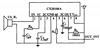
Figure 3 Signal processing circuit
3.3 Ultrasonic signal receiving switch array
In order to avoid the mutual interference between the adjacent ultrasonic receiver and the ultrasonic transmitter or ultrasonic transceiver, the system sets two working modes: time-sharing measurement mode and frequency division measurement mode. When the time-sharing measurement method is used, the ultrasonic receiver and the ultrasonic transmitter select a frequency device. The ultrasonic signal receiving and switching circuit is shown in Figure 4.
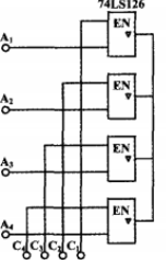
FIG. 4 Ultrasonic signal receiving switching circuit
The logic level sent by the microprocessor controls 74 / _5 126 gated ultrasonic receiver array in odd rows and odd columns, even rows and even columns, odd rows and even rows and odd rows work in turn, and the number of people in the entire area is measured in 4 times. When the system works with the frequency division measurement method, the ultrasonic receiver and ultrasonic transmitter or ultrasonic transceiver choose four devices with different frequencies, and the frequencies between each group of devices with odd rows, even rows of even rows, odd rows of even rows and odd rows of even rows are different. All devices in the group have the same frequency.
3.4 Displaying the Driver Module
The display driver includes a display driver chip MAX7219 circuit and 4 digital tube displays, and the connection with the single chip requires only 3 lines: LOAD (CS) plate selector pin, CLK serial clock pin, DIN serial data pin. The circuit of the driver module is shown in Figure 5.
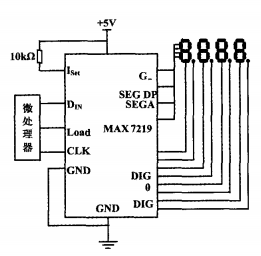
Figure 5 shows the driver module circuit
4 Software Design
The system software includes main program, ultrasonic transceiver subroutine, digital display subroutine and output result subroutine. Initializes the main program and calls the subroutine.
After starting the program, the system first initializes the program, and then sets the parameters with the corresponding timer. After that, the microcontroller generates a series of 40 KKH z ultrasonic waves and activates the timer. Due to the reflective structure of the ultrasonic waves emitted and received, they are in the same line and the two probes are relatively close to each other. In order to avoid the shadow of the transmitting probe on the receiving probe, it is necessary to delay the start of the ultrasonic receiving detection program. The microprocessor switch array selects the appropriate channel to receive the ultrasonic signal. If there are multiple received signals, select the cyclic scanning mode. After calculating the distance, take the sum of the numbers in the indefinite range until the switch is switched one by one. The resulting data is displayed through a digital display tube.
5 Closing remarks
The digital automatic detection system introduced in this paper is based on ultrasonic sensor array, which has the characteristics of simple installation, high measurement accuracy and good stability. It is suitable for bus, elevator and other places that need to be scheduled according to the number of people, so that the vehicle or elevator scheduling is optimized. Avoid resource consumption. The system design has been patented.
The number of people in a system statistics area is measured at an interval of 0.5s. Based on the changes in the location data of people measured twice before and after follow-up processing, the movement of people in the area can be obtained, as well as the situation of people entering and leaving the area.
At present, ultrasound has been applied in many fields such as reversing radar, blind guide system, and autonomous vehicle. The compatibility of this system with other systems needs to be further studied.
reference
[1] Zhang Chunhua, Xie Yongjun, Zhou Zhengyi, et al. Design of a statistical system for detecting people in Public Places [J], Journal of Guangdong University of Technology, 20 12, 29 (3) : 63-67. (in Chinese)
[2] Zhao Jiong, Lin Wangcheng, Jia Peiyuan, et al. Research on the number of people in Public Entertainment venues [J]. Automation Instrument, 2009, 30 (6) : 62 -- 65.
[3] Liu Ziyuan, Jiang Chengzhi. Image number detection based on O penCV and aar feature classifier [J]. Journal of University of Science and Technology Liaoning, 20, 11,34 (4) : 384-388.
[4] Li Meiying, Yin Jun, Bo Feiba, et al. Blind guide system design based on ultrasonic sensor array [J]. Chinese Journal of Medical Equipment, 20, 14, 29 (10) : 28 -- 31.
[5] Liu Qin, Zhang Fengsheng, Liu Dawei. Research on obstacle position calculation method based on ultrasonic sensor array [J]. Journal of Qingdao University: Engineering and Technology Edition, 20O5, 20 (2) : 75-79.
[6] Pan Zhongming, He Hangen. Ultrasonic array obstacle detection technology and its application in unmanned vehicle [J]. Journal of National University of Defense Technology, 2009, 31 (2) : 121-125.
[7] Qin Wei, Yan Wenjun, Design of ultrasonic astern Radar based on CX 20 106A [J]. Electricity & Acoustooptics, 20 11, 33 (1) : 161-164. (in Chinese)
[8] Guo Qing. Design of ultrasonic ranging anti-collision system based on STC89C52 [J]. Meter Technology and Sensors, 2011 (6) : 74-77.
[9] Bu Yongdao, Wang Jichan, Zhao Haiming, et al. High precision ultrasonic ranging system based on monolithic machine [J]. Instrument Technology and Sensors, 2007 (3) : 66-68.
[10] Wang Xijun, Jiang Jun, Sun Fudong, et al. Application of Display driver MA X 72 19 in monolithic sets [J]. Automation Technology and Application, 2009, 28 (1O) : 121-123.
[11] Ma Yin-yuan, Liao Li. Ultrasonic Sensor Array number automatic detection system: China, 20 14 2000 7 3 600. 6 "P]. 2 0 14-0 5-1 1.