


Obstacle avoidance car based on ultrasonic sensor
1 Introduction
Obstacle avoidance car to single-chip microcomputer as the control core of the car changes the traditional remote control of small car control mode, the application of ultrasonic ranging technology combined with the car to achieve automatic obstacle avoidance, so that the car can be more intelligent, the car in the process of moving to reduce human intervention.
2. Design the overall system scheme
2.1 Design Scheme
(1) Through the infrared remote control button control car action, such as forward, backward, stop, left and right turn.
(2) When the distance from the obstacle is less than the set distance, turn left; After turning left, judge whether the distance from the obstacle is large. If it is larger, move forward; otherwise, turn right 180 degrees; After turning right, judge whether the distance between it and the obstacle is large. If it is larger, move forward. Turn right 90 degrees and move forward.
2.2 System Structure
SCM control is simple, convenient and fast. Low price and other advantages. The monolithic machine is used as the core of the whole system to control the car movement. The control system structure.
The design system takes 89C51 microcontroller as the core, and uses infrared remote control to control the start and stop of the car, which can realize the start and stop of the car, turn left and right, go straight and backward and other functions [1].
The ultrasonic transmitting and receiving device in the middle of the head detects the obstacles in the direction of the car and is used to judge whether to turn or not to achieve the obstacle avoidance function. The microcontroller sends out a frequency of 40 kilohertz signal, amplified by the circuit after the ultrasonic transmitter sent out; The ultrasonic receiver further amplifies the received signal, uses the phase-locked loop circuit to detect the wave, calls the interrupt program of the single chip microcomputer, measures the time t, and then obtains the distance parameter by the program, and then processes the data through the single chip microcomputer to control the motor of the car accordingly [2-3].
3. System hardware circuit design
3.1 Infrared Receiver
The infrared receiver circuit is usually integrated in a single component, the infrared receiving head. Internal circuits include infrared monitoring diodes, amplifiers, limiters, bandpass filters, integrators, comparators, etc. [4]. After the infrared monitoring diode monitors the infrared signal, the amplifier amplifies the infrared signal through the limiter, demodulation circuit and integration circuit into the comparator, the comparator output high and low level, restore the transmitted signal. The module uses infrared receiving head 1838. The circuit is shown in Figure 2.
In Figure 2, C3 is the decoupling capacitor, which filters out the interference of the output signal. The first end is the output end of the demodulation signal, which is connected with the P3.2 port of the single chip microcomputer. When the infrared coded signal is emitted, the square wave signal after detection and shaping is processed by the infrared joint and sent to the single chip microcomputer to perform the corresponding operation, so as to realize the motor control.
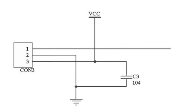
Figure 1 Infrared receiving module
3.2 Motor drive module
The module uses the chip L298, L298 chip is a high voltage, large current double full bridge driver can control the positive and negative rotation of two motors and adjust the motor speed, meet the design requirements. The circuit diagram of the motor drive module is shown in Figure 2.
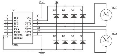
Figure 2. Motor drive module
In Figure 2, the L298DE VCC terminal shares 5V DC power supply with the MCU, and the VS terminal is connected to 12V power supply. ENA, ENB Indicates the enable terminal. Output is disabled at low level. IN1, IN2, IN3 and IN4 are data input pins, which are respectively connected to the P1.0, P1.1, P1.2 and P1.3 ports of the single chip microcomputer. OUT1, OUT2 is connected with motor MG1; OUT3, OUT4 Connect to motor MG2. By adjusting the input high and low levels between IN1, IN2, IN3 and IN4, the forward and reverse operation of motor MG1 and MG2 can be realized, so as to realize the functions of car rotation, forward and backward. When IN1 input low level, MG1 motor turn positive; When IN2 enters low level, MG1 motor reverses; When IN3 input low level, MG2 motor will turn positive; When IN4 input low level, MG2 motor reverses. When high level input, the motor does not work. D1~D8 are protective diodes, which are used to protect L298 from damage when the motor is under emergency braking.
3.3 Ultrasonic Module
BNCS ultrasonic ranging module is adopted, including ultrasonic transmitter, receiver and control circuit [5]. Basic working principle: (1) Using IO port TRIG trigger ranging, to at least 10us high voltage plain message. (2) The module automatically sends 8 40khz square waves to detect whether there is a signal return; (3) There is a signal return, and a high level is output by ECHO through the IO port. The duration of the high level is the time from ultrasonic transmission to return. Test distance =(high level time * sound speed (340M/S))/2. The circuit of ultrasonic ranging module is shown in Figure 4.
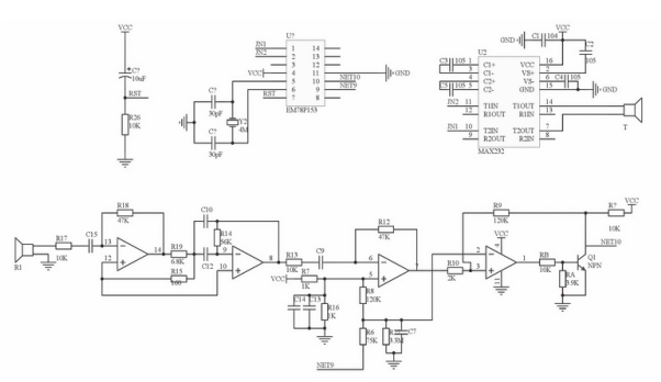
Figure 3 Ultrasonic module
4 System software design
4.1 Main Program
After the program starts, it begins to detect the infrared receiving module. If the signal is received, the MCU begins to judge the key value, and sends a signal to the driving module to make the car and make the corresponding action. When the car moves forward, the ultrasonic module begins to send a signal, the MCU judges the distance from the obstacle, sends a signal to the driving module and makes the car avoid the obstacle.
4.2 Ultrasonic Obstacle Avoidance process
In the obstacle avoidance process shown, the car will detect the obstacles in front when it starts to move forward. If there are any obstacles, it will turn left and continue to detect them. If there are any obstacles, it will reverse 180°; if there are none, it will continue to move forward.
5 Driver module simulation
Protel software is used to simulate the car control system, and the simulation circuit is shown in Figure.
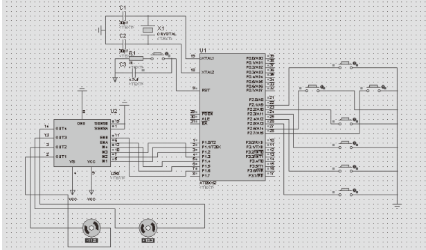
Figure 5 Driver module simulation
During simulation, red indicates high level and blue indicates low level. As the simulation software can not simulate infrared remote control and photoinductive signal and ultrasonic detection, so in the simulation process to provide various signals required by the key. No. 2 button to achieve the car forward function, No. 8 button to achieve the car backward function, No. 5 button stop, No. 4 button car left, no. 6 button car right turn.
6 Closing remarks
The control system of the car uses the single chip microcomputer as the control core, and uses the ultrasonic ranging module to detect the obstacles in the direction of the car. After processing, the single chip microcomputer issues an instruction to drive L298, and the driving motor continues to run to avoid the obstacles. Simulation software is used to simulate the design, and the simulation results show that the design meets the requirements.
Reference literature
[1] Zhao Hailan. Design of infrared Remote Control Intelligent Car based on single Chip Microcomputer [J]. Electronic World, 2011 (8): 45-47.
[2] Wang Yichuan. Ultrasonic ranging alarm System based on MCU control [J]. Shanghai Metrology and Measurement, 2011 (5): 53-56.
[3] Li Lufeng. Design of ultrasonic ranging Control System based on AT89C51 [J]. Manufacturing Automation,2012(4):45-47.
[4] Zhu Gaowei. Control System of Automatic Blocking Mobile Car based on Single Chip Microcomputer [J]. Communications World: the Second Half of the month, 2015 (8): 277-278.
[5] SU Lin. Design of Ultrasonic Rangefinder Based on HC-SR04 [J]. Science and Technology Information, 2012 (9): 125-125.