


Application of ultrasonic sensor in obstacle avoidance system of intelligent car
0 Introduction
Intelligent car, namely wheeled robot, is a kind of mobile robot, is a collection of environmental perception, dynamic decision and planning, behavior control and execution of a variety of functions in one integrated system. With the development of computer science, it can be controlled by single chip microcomputer to realize the driving direction, start, stop and speed control, without manual intervention, the operator can change its driving mode by modifying the control program of the intelligent car. The obstacle avoidance movement of mobile robot has always been an important subject. The main methods of obstacle avoidance are ultrasonic obstacle avoidance, visual obstacle avoidance, infrared sensor, laser obstacle avoidance, proximity sensor, microwave radar and so on. At present, ultrasonic obstacle avoidance is convenient, simple calculation, easy to achieve real-time control, and can meet the practical requirements in terms of measurement accuracy, so it has become a common obstacle avoidance method.
1. Composition and working principle of ultrasonic ranging system
Five ultrasonic sensors respectively measure the distance of obstacles on the left, left front, right front and right side of the car, and take corresponding obstacle avoidance measures according to the measured data. The position of ultrasonic sensor is shown in Figure 1.
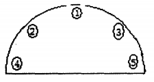
Figure 1 Position setting of ultrasonic sensor
The emitted ultrasonic waves travel straight through the air in all directions and can reflect off obstacles. After receiving the ultrasonic wave from the transmitter, the receiver makes the internal resonator resonate, converts the acoustic energy into an electrical pulse signal through the acoustical conversion, and then inputs the signal amplifier, and finally drives the actuator to make the circuit operate. This paper uses the transit time method, that is, through detection
The time difference △t between the emitted ultrasonic wave and the echo generated after encountering the obstacle is calculated, and the distance d of the obstacle is calculated. The calculation formula is d = C* △t / 2, where c = 331.4, / 1 + T / 273 is ultrasonic wave velocity, and T is ambient Celsius temperature. In use, if the temperature changes little, it can be considered that the speed of sound is basically unchanged; But if the ranging accuracy is very high, it should be corrected by temperature compensation method.
The ultrasonic generator generates 40kHz square wave, which drives the ultrasonic sensor at the transmitting end after pulse modulation and sends out sinusoidal wave with the same frequency. At the arrival of each modulated pulse, the transducer emits 8 to l2 cycles of ultrasonic waves, while starting the MCU counter timing. The ultrasonic wave is reflected by the measured target and converted into an electrical signal by the sensor at the receiving end. After processing the circuit, an interruption is generated. At the same time, the MCU stops counting and then calculates the distance of the obstacle by counting the difference.
2 Circuit Design
2.1 Ultrasonic generating circuit
As shown in FIG. 3, according to the working characteristics of the ultrasonic sensor, NE555 is selected to generate 40K square wave, duty cycle is 50%, and supply voltage is 5V. The pulse modulation is realized by the reset (RST) pin of NE555 controlled by the single chip PI.0 port. When P1.0 =1, pin 3 output 40kHz square wave, lasting 8-12 cycles. If the number of sustained cycles is too small, it is difficult to stimulate the ultrasonic probe normally, if too much, the transmitted wave and reflected wave are easy to produce superposition interference, when P1.0 = 0, no signal output of pin 3. The low level duration is determined by the measuring distance. The larger the measuring distance, the longer the low level duration.
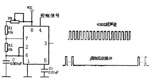
Figure 3 Ultrasonic generator and signal before and after modulation
2.2 Circular receiving and transmitting circuit
The cyclic transmitting circuit mainly uses a multi-channel analog switch CD4051 to control the transmitting sequence, as shown in FIG. 4. IN H is the control input pin. When the pin is logical high power level, all channels are closed. Otherwise, the opening state of the channel is controlled by address selection terminal A to C. The control signal shown in FIG. 4 is the same as that shown in FIG. 3. At logical high voltage level, pin 3 of N E555 outputs the modulated signal, and CD4051 works normally after being reversed by the inverter. After the completion of the transmission of one transmitter, the control signal output low level reset 555, at the same time, reverse phase applied on the pin IN H of 4051, close all channels.
The circular receiving circuit also uses CD405 1, the circuit is basically the same as the receiving circuit. The receiving circuit and the transmitting circuit use the same address control signal, that is, the transmitting group just corresponds to the receiving group, for example, the No. 1 transmitting sensor corresponds to the No. 1 receiving sensor. The IN H pin of CD405 1 at the receiving end is made by the single chip microcomputer PI. 2 Control: After the pulse transmission of one transmitter is completed, after a certain blind delay, the PI. 2 output low level and connect the corresponding channel. The low level duration is the same as that of the PI.0 control signal. If no echo signal is detected during the low level of the control signal, P1. 2 Output high level forbid receiving again. If echo signal is detected, stop counter counting, read the calculated value, and enter the transmission and receiving of the next channel.
2.3 Receiving and processing circuit
As shown in Figure 5, the ultrasonic receiving circuit is generally composed of the following parts: preamplification, amplitude limiting amplification, bandpass filtering, peak detection, and Schmitter shaping output circuit. In order to reduce interference and have sufficient amplification gain, the circuit can be greatly simplified to make the system more stable. This paper uses the infrared receiving circuit chip CX 20106. The chip is an infrared ASIC produced by SONY in Japan, which can also be used for ultrasonic detection.
The signal received by the ultrasonic receiving end is coupled by the capacitor C4 and then input to the first end. The total gain size is determined by the resistance and capacitance of the 2-pin receiver. The parameter is usually selected as R 1 = 4. 7ft, C 1 = II. ~F. Pin 3 is the detection capacitance, the capacitance is the average value of the detection, the corresponding sensitivity of the moment is low; If the capacity is small, it is the peak detection and the instantaneous corresponding sensitivity is high. However, the pulse width of the detection output changes greatly, which is easy to cause misoperation. The recommended parameter is 3.3d. The receiving frequency of the carrier signal can be changed by changing the resistance value. If R = 2~ kf l, fo~ 42 kH z; if R = 220k~, then the center frequency will be 38 kh z. Pin 6 is the integral capacitance, which is generally 330PF. If the capacitance is too large, the detection distance will be shortened. Pin 7 is the output terminal. It is an open-collector output mode, so the pin must be connected with a pull-up resistor to the power terminal. The recommended resistance value is 22kf l. 8-pin power supply. Therefore, if no echo signal is detected during the period allowed to receive, the output of this end will be high level; if there is a signal, it will produce a drop [4]. Therefore, by taking advantage of this feature, the output signal of pin 7 is connected to the Ex of 89C52. When obstacles are detected, Pin 7 outputs a low pulse, and the current values of TL2 and TII2 in timer 2 are self-captured to RCA ~ L and RCA ~ H respectively, causing an interruption at the same time.
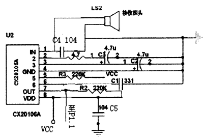
Figure 5 Ultrasonic receiving circuit
3. System software design
This system uses STC89C52 as the main control chip, which has 5 12 K data memory and 8K program memory, and has a total of 3 timers -ID, T1, rI2 for use. The program flow chart is shown in Figure 6. The 40K square wave generated by NE555 passes through P1. After the 0 signal is modulated, select the channel through C ~ 051, and then drive the sensor to emit ultrasonic waves. Ultrasonic encountered obstacles reflected, transmitted to the ultrasonic receiving end, the signal through the infrared processing chip and then sent to the MCU. When c)(20lo6) captures the ultrasonic wave of 40 kH z, its output pin changes from high level to low level, and the negative jump on this pin can be interrupted to cause the interrupt of the MCU. In the interrupt service program, the timer stops counting. The timer timing time is the time difference of ultrasonic wave from transmitting to receiving, and then the measured distance can be calculated according to S = v V 2. Finally, the microcontroller takes corresponding obstacle avoidance measures according to the distance of the obstacle measured by the five sensors.
Error analysis and compensation
The ranging system is generally composed of five parts: ultrasonic transmission, reception, time measurement, microcomputer control and distance calculation. The commonly used measures to improve the measurement accuracy include improving the timing accuracy reducing the time quantization error and compensating the influence of temperature on the propagation velocity. Because the system does not require high precision, single chip microcomputer can be used for timing and think that the ultrasonic speed is constant.
5 Conclusion
In this paper, the automatic obstacle avoidance system of intelligent car is designed. The system has the advantages of simple design, low cost and good real-time performance. The expected experimental results are obtained in indoor environment, so that the intelligent car can avoid obstacles without collision. The system has strong anti-interference ability, simple control process, high precision and low cost outstanding characteristics, can be widely used in access control system, small area patrol, field survey, intelligent toys and other fields, broad market prospects, has great economic benefits.