


Evaluation of horizontal control system performance of paddy field Laser Grader by ultrasonic sensor
Introduction
In order to save agricultural water and improve the efficiency of the use of pesticides, fertilizers and herbicides, more and more attention is paid to the fine leveling of farmland. Laser-controlled leveling technology for farmland leveling can effectively improve the accuracy of farmland leveling and the utilization rate of farmland irrigation water, so as to realize fine surface irrigation [1-3]. Laser grader has been applied in dry land leveling [4-6]. The hard bottom of paddy field in south China is uneven, so the laser grader for paddy field was developed by Engineering College of South China Agricultural University. In the paddy field leveling operation, the laser grader not only realized the adjustable level of the grader, but also ensured the controllable level of the grader, so that the grader always kept on a plane parallel to the laser beam plane during the working process [7~ 8]. The results of large-scale production experiment show that the leveling accuracy of paddy field laser grader can well meet the agronomic requirements of rice planting [9]. In order to evaluate the detection and control performance of paddy field laser grader's dip Angle, two ultrasonic sensors were used to evaluate the detection and control performance of paddy field laser grader's dip Angle.
1. Principle of ultrasonic sensor for measuring inclination Angle
1.1 Principles of ultrasonic ranging
The basic principle of ultrasonic ranging is that ultrasonic transmitting sensor sends out sound waves, sound waves meet the measured object to return to the ultrasonic receiving sensor, according to the transmission time of sound waves, the measured distance can be calculated
Where c is the propagation velocity of sound wave in air, c= 343 m/ s at 20 e, a standard atmospheric pressure.
1.2 Principle of ultrasonic inclination Angle measurement
Ultrasonic waves can be used for object tilt measurement [10]. As shown in FIG. 1, an ultrasonic sensor is installed at each end of the measured object. By measuring the distance between the two ends of the measured object and the reference horizontal plane, the tilt Angle of the measured object can be obtained. The included Angle between the measured object and the reference plane is the Angle H in the figure. Suppose the distance measured by ultrasonic sensor 1 and ultrasonic sensor 2 are L1 and L2 respectively, then the relation between the tilt Angle H of the measured object and L1 and L2 is
2. Influencing factors of ultrasonic sensor measurement
2.1 Influence of temperature on distance measurement
It is generally believed that when ultrasonic waves propagate through the air, the propagation speed of sound is affected by the ambient temperature. The relation between sound velocity and temperature is T))) Celsius temperature, e

In order to reduce the ultrasonic propagation speed in the air affected by the environment, the digital temperature sensor DS18B20 is used to detect the environment temperature to achieve temperature compensation, and the temperature resolution can reach 015e. To understand the range measurement accuracy of the SensComp 600 ultrasonic sensor, the sensor was fixed at a height of 800 mm and sent sound waves vertically to the ground. FIG. 2 shows the distance data curve measured by the ultrasonic sensor for nearly 30 minutes continuously. As shown in the figure, the SensComp 600 ultrasonic sensor measured distance with high accuracy under static conditions, with an average error of 0102 mm and a maximum error of 8 mm.
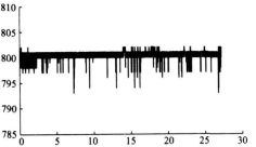
Figure 2 Static distance measurement of ultrasonic sensor
2.2 Effective Angle of normal echo reception
When the ultrasonic sensor is used to measure the tilt Angle of the object, the sound wave will inevitably form a certain Angle with the reflective surface (reference plane), as shown in Figure 3. If the tilt Angle is too large, the echo cannot be received. The maximum effective tilt Angle measured by the SensComp 600 ultrasonic wave sensor was A= 2216b.
2.3 Influence of motion on echo reception
As the ultrasonic sensor moves relative to the ground in the measurement process, there will be a phenomenon that the frequency of the received sound wave is different from that of the transmitted sound wave, namely Doppler effect [12]. The relation between the frequency of sound wave transmitted from the sensor to the ground and the frequency received by the ground is

The sound wave is reflected from the ground to the sensor, and the sensor receives a frequency of


When the sensor faces the direction of motion, minus sign is taken in the formula; Conversely, when the sensor faces the opposite direction of motion, the plus sign is taken.
The experiment shows that the ultrasonic sensor has no influence on the normal echo reception because of its low velocity with the shovel.
2.4 Comparison with attitude sensor
In order to verify whether the ultrasonic sensor can accurately measure the tilt Angle, the attitude and headingreference system AHRS500GA2226[13] is used as the reference sensor. The sensor measures the Euler azimuth (course, pitch and roll Angle) of the object to be installed. It has built-in three-axis magnetic field meter, three gyroscopes and three accelerometers, which can measure the azimuth in the 360b range with high precision and high sensitivity. In this experiment, its Y-axis is installed along the length direction of a long board. The pitch Angle measured is the actual dip Angle of the board. The two ultrasonic sensors are respectively installed at both ends of the board, with a distance of 2185 m and a height of 017 m above the ground. MCU C8051F040 realizes the control of ultrasonic sensor, the calculation of distance and Angle, and saves the pitch Angle of AHRS500GA2226, and sends it to the computer through RS232.
As shown in Figure 4, it is the tilt Angle of the board measured by ultrasonic sensor and AHRS500GA2226 respectively. The experimental results show that the maximum deviation of static measurement is 0108b when the tilt Angle is measured by two ultrasonic sensors. Maximum deviation 1100b during dynamic measurement. Therefore, the motion of the sensor has little influence on the accuracy of ultrasonic ranging. It is feasible to measure the tilt Angle with two ultrasonic sensors.
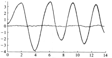
FIG. 4 Contrast curve with attitude sensor
3. Experimental platform and performance evaluation experiment
3.1 Paddy field laser Grader platform
The paddy field laser grader evaluated in this paper consists of two parts: elevation control part and level control part [8]. The leveling shovel and the seedling transplanting machine chassis are connected through three-point suspension, and the elevation controller controls the expansion and expansion of the double-acting oil cylinder according to the laser signal from the laser transmitter measured by the laser receiver, so as to realize the hoisting or descending of the leveling shovel, so as to ensure that the leveling shovel is at the set height. The whole shovel (shovel length 3) can be rotated relative to the suspension device. The dip Angle of the shovel is obtained by the horizontal control system and the signals of M MS inertial sensors (accelerometer DXL 3 and gyroscope DXRS3) produced by D Company of the United States. The shovel is kept level through the double-acting oil cylinder. Therefore, the level shovel can realize the joint control of height direction and horizontal direction, so that the level shovel is always in a horizontal plane parallel to the laser plane.
3.2 Performance evaluation experiment
In order to evaluate the detection and control performance of the paddy field laser grader's inclination Angle, according to the principle of ultrasonic measurement of inclination Angle, two ultrasonic sensors are installed at both ends of the paddy field laser grader's inclination Angle respectively, as shown in FIG. 5. The two ultrasonic sensors are 2185 m apart. The operation, distance and Angle calculation of ultrasonic wave transducer are completed by the monolithic machine C8051F040. At the same time, the single-chip computer through a serial port to receive the shovel level control system from the shovel tilt information, and through another serial port will be a variety of data real-time output, the PC will save and analyze the data.
During the test, the 3 m long flat shovel was raised to about 015 m above the ground. According to the experimental scheme, the shovel was manually shaken (the shovel made plane motion), and the ultrasonic test system collected and recorded real-time data.
4 Conclusion
(1) It is feasible to use two ultrasonic sensors to measure the tilt Angle, and the static and dynamic measurement accuracy are 0108b and 1100b respectively.
(2) A low-cost accelerometer ADXL203 and a tortilla instrument ADXRS300 are used for the inclination Angle of the paddy field laser grader. The real-time inclination Angle of the grader can be accurately obtained through the fusion of Angle information, and the general error is less than 1b.
(3) The level control system of paddy field laser grader can better control the level of the grader and meet the needs of paddy field leveling operation.
Reference literature
1 Agarwal M C, GoelA C. Effect of field leveling quality on irrigation efficiency and crop yield [ J] . Agricultural WaterManagement, 1981, 4(1~ 3) : 89~ 97.
2 Inney C. T he benefits of land leveling on ir rigation schemes in Turkey and Sindh Province, Pakistan[ J] . ICID Jour nal,1996, 45( 1) : 1 523~ 1 539.
3 Xu Di, Li Yinong, Li Fuxiang, et al. Application of conventional land leveling Technology and laser Leveling technology [J]. Transactions of the Chinese Society of Agricultural Engineering, 1999, 15(10) :51~ 56.Xu Di, Li Yinong, Li F uxiang, et al. Study on combination of conventional and laser controlled land grading pr ocedures[ J] .Transactions of the Chinese Society of Agricultural Engineer ing, 1999, 15( 10) : 51~ 56. ( in Chinese)
4 Rickman J F . Manual for laser land leveling[ R ] . Rice2wheat Consortium Technical Bulletin Series 5, 2002.
5 Liu Gang, Lin Jianhan, Si Yongsheng, et al. Design and experimental analysis of laser controlled Leveling System [J]. Transactions of the Chinese Society for Agricultural Machinery, 2006, 37(1) : 71~ 74.Liu Gang, Lin Jianhan, Si Yongsheng, et al. Development and experiment on laser controlled leveling system [ J ] .Transactions of the Chinese Society for Agricultural Machinery, 2006, 37( 1) : 71~ 74. ( in Chinese)
6 Chen Xuewen, Wan Xinjun. American VC3S1722/4VDC Paddy Field Laser Grader [J]. Modern Agriculture, 2001(4) : 37~ 38.Chen Xuewen, Wan Xinjun. American VC3S1722/ 4VDC paddy laser leveling system [ J] . Modernizing Agr iculture,2001( 4) : 37~ 38. ( in Chinese)
7 Zhao Zuoxi, Luo Xiwen, Li Qing, et al. Water Level Control System of Paddy Field Laser Leveling Machine Based on MEMS Inertial Sensor Fusion [J]. Transactions of the Chinese Society of Agricultural Engineering, 2008,24(6) : 119~ 124.Zhao Zuoxi, Luo Xiwen, Li Qing, et al. Leveling control system of laser2controlled land leveler for paddy field based onMEMS inertial sensor fusion[ J] . Transactions of the Chinese Societ y of Agricultural Engineering, 2008, 24( 6) : 119~ 124.( in Chinese)
8 Luo Xiwen, Zhao Zuoxi, Li Qing. Study on leveling control for a paddy laser leveler [ C] M 2007 ASAE Annual Meet ingPresentat ion Paper , No. 071078, 2007. 3() ~ 3()(next page)76 Transactions of the Chinese Society for Agricultural Machinery 209
9 . J . 2007 2 4 : 88 9 .i ing uo iwen ang aohua et al. esign o a laser land leveler or padd ield J . ransactions o the Chinese
10 Gordon McComb. Robot builder. s sourcebook[ M] . McGraw2Hill eBook, USA, 2003.
11 R oland Siegwart, I llah R. Nourbakhsh. Introduction to autonomous mobile robots[ M] . London: T he MIT P ress, 2004.
12 Chi Anshen and Du Chanying. General Physics Course: Mechanics [M]. Beijing: Higher Education Press, 1997.
13 Crossbow Technology Inc. . AHRS500GA2[ ] user. s manual, revision B[ M] . USA, 2007.