


Design and test of high reliability differential pressure sensor
Pressure difference sensor is used to measure the pressure difference between two cavities of servo system actuator. Aiming at the application requirements of high reliability, high precision, high temperature resistance and miniaturized pressure difference sensor, the design scheme of high reliability pressure difference sensor is proposed and tested, including core design, structure design and circuit design. The product uses SOI silicon wafer material to make pressure sensitive chips, which can work normally at 150 ° C. The sensor has passed the performance test and environmental test, and the test results show that the sensor can meet the actual use requirements, and the temperature drift and sensitivity drift are less than ± 0.1% FS / ℃ at 150 ℃.
0 Introduction
The pressure difference sensor is an important component of the hydraulic servo system. The sensor converts the pressure difference signal of the two cavities of the actuator into a standard voltage signal and sends it to the controller to realize the control of the system. The reliability and accuracy of the sensor will directly determine whether the servo system can work reliably [1]. Aiming at the application requirements of high reliability, high precision, high temperature resistance and miniaturized pressure differential sensor in some special engineering fields, a design scheme of high reliability pressure differential sensor is proposed. The sensor can work stably at 150 ℃. The reliability of the sensor is verified by experiments, and it can meet the requirements of practical engineering.
1 Sensor design scheme
1.1 Overall Design
As the measurement pressure range is ±25 MPa pressure, the use of one core to measure the pressure difference cannot achieve reliable measurement, so the sensor adopts a dual-core structure, through two pressure-sensitive cores respectively feel the pressure at the high and low ends and convert them into two voltage small signals. Then the two small signals are temperature compensated, and the last two signals are differentially processed, and the sensor outputs the difference signal. It mainly includes the core body pressure sensing part and the circuit conditioning part.
1.2 Pressure sensitive core
The sensitive core is the core of the sensor, and its function is to convert the pressure of the measured medium into an electrical signal. In order to meet the needs of high temperature use, the pressure sensor adopts SOI chip. The structure of SOI chip is the substrate silicon as the mechanical support, the top layer of monocrystal silicon film is used for manufacturing devices, and the insulating medium in the middle is used as the isolation layer. SOI chip uses silicon oxide to achieve electrical isolation between sensitive resistors and substrate, replacing the traditional diffusion silicon PN junction electrical isolation technology, and therefore has good high temperature working characteristics [2].
The pressure-sensitive core adopts an isolated and sealed charging structure [3], as shown in Figure 2, which is mainly composed of chip, tube base, diaphragm, etc. The sensitive chip is mounted on a high temperature resistant metal tube base with high temperature adhesive. The chip and the metal outer lead are connected through the gold inner lead, and the process is mature and reliable. The metal outer lead is connected and fixed with the tube base by the metal-glass sealing process, which has high mechanical strength, high temperature resistance and good sealing property. Stainless steel corrugated diaphragm separates the sensitive chip from the measured medium to avoid the chip being affected by the medium; The incompressible filling liquid is pumped into the pressure chamber after vacuum purification, and the filling circuit is sealed by sealing oil beads after filling. When the pressure is applied to the corrugated diaphragm, the pressure sensitive chip is sensed by silicone oil and an electrical signal is generated.
1.3 Sensor mechanical structure design
The structural design of the sensor is based on the design principle that can meet the engineering application, especially for the requirements of external size, weight and high overload capacity (should be able to withstand the rated pressure of 80 MPa). The pressure difference sensor is designed into a dual-core, all-solid and symmetrical structure. The sensor structure is shown in Figure 3, which is mainly composed of the top cover, base, circuit board, tight wire tube and high temperature cable. The dual core is designed to meet the pressure difference signal for measuring large pressures, and the dual core is matched after strict screening and symmetry selection.
Sensitive core A and sensitive core B are connected to the base by electron beam welding. After the first piece is welded, the weld shall be cut and metallographic analysis, and the weld shall be uniform and smooth, and the weld depth shall not be less than 2 mm. The circuit board is fixed by screws on the circuit board mounting step inside the base. The cable is drawn from the cable bundle tube. There is a round hole above the tight tube, and a threaded hole is provided at the corresponding position in the base. When the sensor is assembled, the pressure screw is threaded downward through the threaded hole in the base, and the cable is squeezed downward through the round hole of the tight tube. The top cover is fixed to the base by screws.
1.4 Sensor circuit design
The signal output of the differential pressure sensor is analog voltage output, and the design of the sensor circuit is mainly divided into temperature compensation module, differential processing module and circuit protection module.
The sensor temperature compensation module uses digital compensation technology to accurately compensate the output signal of the sensor core, and modulates the sensor zero output value and full scale output value to the nominal value [4]. This paper uses a special temperature compensation chip MAX1452, which includes data processing, analog-to-digital conversion, digital-to-analog conversion and internal data storage. The chip uses the resistance of the bridge arm in the pressure sensitive core to detect the ambient temperature, and then converts it into a digital signal through ADC and transmits it to the temperature indicator register to form a temperature indicator pointer. According to the change of temperature, the calibration coefficient of the corresponding temperature point is retrieved in the internal E2PROM query table, loaded from E2PROM to the corresponding register through the serial data interface, and then converted to analog by DAC to correct the temperature drift of full scale and zero point in the output signal of the sensor.
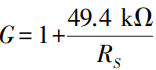
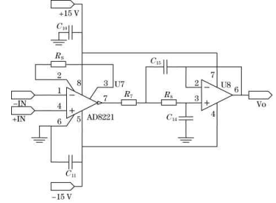
The differential processing module performs differential processing on the measured signal after two temperature compensation channels. Differential processing includes core differential, amplification and low-pass filtering. The chip AD8221 is a gain programmable, high performance instrument amplifier, operating temperature range is -40 ~ 125℃. The principle of differential processing circuit module is shown IN Figure 4. Pin 1 and pin 4 of instrument amplifier AD8221 are connected with 2 pressure measurement signals -IN and +IN respectively. The resistance RS of the 2-pin and 3-pin connection sets the amplification factor, and the calculation formula of the amplification factor G is
6 pin set output grounding; Pin 8 and pin 5 are respectively connected to ±15 V power supply. The low-pass filter circuit is a 2-order active low-pass filter circuit, and the signal cutoff frequency is set by setting the resistor R7, R8 and the capacitor C14, C15.
2 Sensor development and performance test
The output voltage signal is -2.5 ~ +2.5V, and pmax is the full pressure value of the sensor.
At room temperature, the pressure calibration of the sensor was carried out on the piston manometer for 3 times, and the pressure calibration point of each stroke was 11. The indicating value calibration starts from the lower limit of the measurement range, steadily increases the load according to the specified calibration point, until it reaches the upper limit of the measurement range (called positive stroke), and then returns to the upper limit when the upper limit load fluctuates upwards by about 2%. At this time, the output value read is used as the initial value of the reverse stroke and is calibrated in the order of the original calibration point (called reverse stroke). The calibration curve of the sensor is formed by connecting the average value of the calibration points. The actual working straight line is realized according to the least square method adopted by the calibration data. The working straight line of the sensor can be expressed as
Where: a is the intercept of the working line (the zero point of the sensor); b is the slope of the working line (sensitivity of the sensor).
Based on the calibration data, the intercept and slope can be obtained by the following formula.
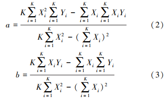
Where: K is the number of pressure calibration points; Yi is the sensor output (calibration data) for each calibration point.
In order to meet the requirements of high test stability of the servo system, the performance test of the sensor is carried out. In addition to checking the static characteristics of the sensor, including the basic indicators of zero position, positive pressure and negative pressure full output voltage, accuracy, nonlinearity, sensitivity, symmetry, etc., the stability of the sensor is also verified by zero drift, thermal zero drift and thermal sensitivity drift. To ensure that the sensor can have a good working condition in high and low temperature environment
State. The actual performance of the sensor is shown in Table 1, and the test shows that the sensor has excellent temperature characteristics.
3 Reliability test
Environmental adaptability can be verified by environmental testing, which means that products or materials are exposed to natural or artificial mechanical environments to verify the performance of sensors in actual storage, transportation and use environments [5]. According to the environmental requirements of a project, various tests are carried out on the designed sensor, and the test results show that the product has good stability and can meet the requirements of use. The reliability test of pressure sensor includes mechanical environment test, natural environment test and life test.
3.1 Mechanical environment test
The mechanical environment test of the sensor includes vibration test, simulated transport test, impact test and overload test. The test was carried out in three directions orthogonal to each other. The vibration test and the simulated transport test are carried out on the induction electric vibration table, the impact test is carried out on the drop impact table, and the overload test is carried out on the medium-sized centrifuge. The test directions are all along the 3 directions orthogonal to each other of the product. During the test, the sensor is powered on to test, and the sensor output should meet the requirement of zero output, and the appearance of the sensor is without damage.
After the test, check the appearance of the sensor, and power up to test the zero-point output of the sensor under conventional conditions (temperature: 20 ℃, humidity: 30%).
3.2 Natural environment test
The natural environment tests carried out by the sensor include thermal vacuum test, low pressure test, temperature cycle test, alternating humid heat test, high temperature test, low temperature test, temperature shock test, aging test, mold test and salt spray test. During the test, the product is tested in the environmental test chamber. After the test, the performance indicators of the sensor were tested by power on under conventional conditions (temperature: 20 ℃, humidity: 30% ~ 50%). The results were basically consistent with those before the test, indicating that the sensor could withstand the assessment of natural environment test. The high temperature test temperature of the sensor is 150 ℃, the holding time is 2 h, and the product is powered on during the test, and the zero temperature drift is less than ± 0.1% F.S / ℃.
3.3 Life test
The life test of the sensor includes mechanical fatigue test and electrical working life test. The mechanical fatigue test is to install the pressure difference sensor on a special pressure fatigue machine, and fill the degree pressure in the positive and negative direction at the same time, the pressure tolerance is ± 10%, the frequency is 1 ~ 2.5Hz, and the fatigue number is 20,000 times. Electrical working life is under conventional conditions (temperature: 20 ℃, humidity: 30% ~ 50%), the sensor power time is not less than 1000h. After the test, the performance indicators of the sensor were tested by power on under conventional conditions (temperature: 20 ℃, humidity: 30% ~ 50%). The results were basically consistent with those before the test, indicating that the sensor could withstand the assessment of natural environment test.
4 Conclusion
Aiming at the demand of small pressure difference sensor in engineering application, a design scheme of small pressure difference sensor is proposed. The designed sensor adopts double core structure and has simple mechanical structure. The circuit adopts temperature compensation design, high precision in the temperature range. The sensor has passed the environmental test, and the test results show that the sensor can meet the application requirements of extreme environment.
References:
[1] Wu Linghui. Design and characteristic study of high temperature and high pressure difference sensor [D]. Harbin: Harbin Engineering University, 2011.
[2] Sun Ke, Lv Yan, Zhang Dongxu. SOI pressure sensor and its application [J]. Instrument Technology and Sensor, 2010 (4) : 61-64.
[3] Liu Qin, Lv Zhonggang, Chen Yanwen. Study on Structure Design and Packaging Technology of diffused Silicon Pressure Sensor [J]. Instrument Technology and Sensors, 1996 (10) : 18-19.
[4] Liu Peng, Yang Xueyou, Yang Linghui, et al. Design of temperature compensation System based on MAX1452 Silicon Pressure sensor [J]. Instrument Technology and Sensor, 2010 (4) : 61-64.
[5] Wang Zhen, Wang Wei, Yang Ming, et al. Development of back-pressure Silicon Piezoresistive pressure difference sensor [J]. Missiles and Space Launch Vehicles Technology, 2016 (1) : 98-102.