


Design of mine pressure sensor based on CAN bus
In recent years, more and more attention has been paid to coal mine safety production, reducing coal mine accidents and reducing casualties is an important aspect of coal mine production. It is urgent to improve the reliability and accuracy of the coal mine safety monitoring system. As an important part of the monitoring system, the mine pressure sensor has important practical significance to detect the pressure in the underground roadway and pipeline in real time. With the rapid development of MEMS MEMS technology and process, pressure detection components have higher precision and extremely low power consumption, smaller volume and lower cost. The pressure sensor MEAS 1220 produced by Precision Electronics of the United States uses current constant current power supply. It can detect the pressure in the range of 0 ~ 100PSI, the full-scale output voltage is 50mV, and the nonlinearity does not exceed 0.1%. Fully able to meet the sensor design requirements.
Frequency signal, 485 bus and CAN bus are used in the remote transmission of mining sensors at present. CAN bus has greater advantages and wide application prospects compared with frequency signal and 485 bus. The CAN controller works in multi-master mode, and the RS485 bus CAN only work in master-slave mode: The CAN bus node has the function of automatically shutting down the output when there is an error without affecting other nodes. When RS485 nodes send data to the bus at the same time, there will be a bus short circuit, which damages some nodes to lock the bus: CAN bus nodes CAN be point-to-point, one-to-many and broadcast centralized mode to transmit and accept data, with greater flexibility: CAN bus nodes can be designed up to 110. Compared with RS485 bus, CAN bus is used to transmit the pressure signal of the pressure sensor.
The design uses LPC1752 as the core processor of the control, LPC1752 is the Cortext M3 core processor, is designed for embedded system applications and high performance, low power 32-bit microprocessor, suitable for instrumentation, industrial communication, motor control, lighting control, alarm system and other fields. It operates at frequencies up to 120MHz. With a wealth of peripherals, 4 32-bit universal timers, an 8-channel 12-bit ADC, 5 UART interfaces, 2 CAN, 3 SSP interfaces, 1 SPI interface, 3 I2C interfaces, 6 universal PWM outputs, 1 watchdog timer and an independent power supply of ultra-low power RTC, etc. The LPC 1752 can complete the acquisition and processing of analog signal and digital signal independently, and meet the design requirements of mining pressure sensor products.
1 System Structure
The pressure sensor circuit based on CAN bus is composed of core control circuit, power supply circuit, pressure measurement circuit, sound and light alarm circuit, infrared remote control receiving circuit and CAN bus data transmission circuit. The schematic diagram of the system is shown in Figure 1.
2 Design of each module of the hardware circuit
1) Control core module design
The control core module of the sensor takes LPC1752 chip as the control core. The core module is mainly composed of LPC1752 clock circuit, reset circuit and JTAG debugging interface circuit. LPC1752 has high reliability, strong anti-interference ability, high processing speed, stable work, abundant external, etc., and has high real-time performance for pressure collection and data transmission. It can meet the design requirements of pressure sensors. Control core module circuit.
2) Design of power module circuit
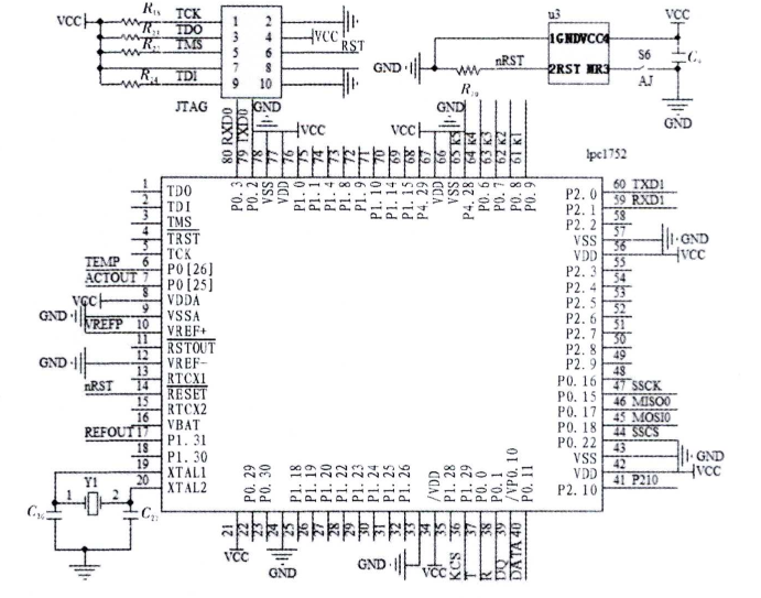
FIG. 2 Schematic diagram of control core
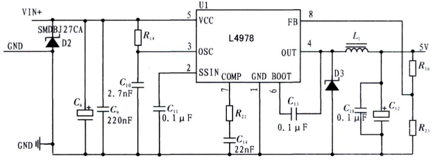
Figure 3 Schematic diagram of power supply
(3) CAN bus module circuit design
The circuit of CAN bus module mainly consists of CAN bus transceiver, signal isolation circuit and transient suppression circuit. CAN bus transceiver adopts PCA82 l2 5l, PCA82C25l is the interface chip between CAN protocol controller and physical bus, with a communication rate of up to 1M baud, supports at least 110 nodes, has strong anti-electromagnetic interference ability, the bus: The power failure or damage of the points will not affect the normal communication of the entire network.
The CAN bus controller of the LPC 1752 sends and receives data from the CAN bus through the CANTD and CANRD pins to prevent voltage fluctuations and high voltage shocks on the bus. In this design, the isolation chip 6N137 is used to isolate MCU and CAN bus. The isolation voltage of 6NI37 can reach 2500VAC and the communication rate can reach 10MBd, which can fully meet the performance requirements and communication requirements of protecting MCU. The output end of the PCA82C251 is connected to the CAN bus through two recoverable fuses, which are in a high resistance state when the current passing through the bus is too large. Protects PCA82C25l.
TVS tubes Dl and D2 are reversely connected between CANH and CANL buses. When the voltage between CAN buses has a transient shock. The TVS tube is broken down and short-circuited to protect the CAN bus transceiver. The reliability and stability of the bus module circuit are improved. One end of the CAN bus is connected with a matching resistance of 120 Ohm to improve the communication distance and stability of the bus. The circuit of the communication module is shown in Figure 6.
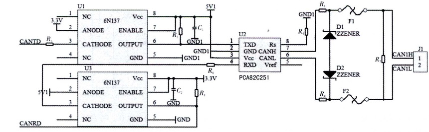
Figure 6 CAN bus transmission module
3. Design of system software
The software design of pressure sensor based on CAN bus includes system initialization configuration program, pressure data acquisition program and CAN bus data transmission program. The initialization service consists of LPC1752 initialization service and CAN bus initialization service.
The LPC1752 collects pressure data in real time through the d module. When the pressure value exceeds the set alarm limit, the controller turns on the audible and visual alarm function, and transmits the pressure value to the mining sub-station through the CAN bus: when the LPC1752 receives the read data command sent back by the CAN bus. The LPC1752 sends the measured pressure data values to the CAN main line. The main control of CAN bus configuration is to complete the baud rate, identifier and data length of the data sent and received by CAN bus. The entire software flow chart is shown in Figure 7.
4 Conclusions
The design of pressure sensor based on CAN bus can better detect the downhole pressure data, and can grasp the information of whether the downhole pressure exceeds the standard in real time. The transmission through CAN bus has the advantages of long transmission distance, stability and reliability, and strong anti-interference ability. Compared with the traditional RS485 bus and frequency signal transmission mode, CAN bus has the advantages of multiple nodes, long transmission distance, reliable communication, etc. It is suitable for the construction of underground monitoring system network. Through the actual field test and aging experiment, the pressure sensor based on CAN bus has a strong real-time to the underground pressure, and can accurately alarm the sound and light according to the pressure change. The transmission distance of CAN trunk line is more than 5 kilometers, and the sensor is stable and reliable. It can meet the design requirements of pressure sensor in monitoring system.