


Research on balanced marching strategy of two-wheeled robot based on dual ultrasonic data fusion
This paper briefly studies the problems existing in the application of the self-balancing machine in labor and delivery, and the control strategy of its structural point and attitude leveling. A balancing operation strategy based on dual ultrasonic ranging data fusion is proposed for balancing and tuning operation of fault protection machine. By combining the dual ultrasonic data with the balance calculation method, the self-balance attitude control is realized on the Arduino main controller, and it is considered that the number of dual ultrasonic sensors is processed. The self-balancing operation of the machine is ensured by the following methods. At the same time, PID control algorithm is added in the operation process of the robot to adjust the operating state of the robot and speed up the processing speed of the robot signal error. The experimental and simulation results show that the strategy is effective and feasible, the dual ultrasonic self-leveling machine maintains a good balance attitude, and its progress control system and basic direction control system are also effective and reliable. It has good stability and balance coordination. Under the control of the balance method, the double ultrasonic machine not only realizes the leveling forward, but also realizes the leveling backward under the running strategy and the leveling turn under the square array direction control. There is a wide range of front views available.
0 Introduction
The two-wheeled self-balancing mobile robot can perform tasks flexibly and quickly in a complex and narrow working environment with large corners. The mobile robot has two wheels in common axis, the center of gravity of the fuselage is placed above the center of gravity of the axle, and the relative balance of the fuselage can be maintained by the forward and backward movement, and the upright walking of dynamic balance can be achieved. Due to its advantages of small size, flexible movement and strong ability to adapt to terrain changes, two-wheeled self-balancing mobile robots can complete some tasks in narrow environments [1,2]. In a complex environment, it is necessary for a self-balancing robot to sense the environment efficiently and adjust its posture in time. Due to the limited sensing ability of a single sensor (such as ultrasonic sensor), it is necessary to interact with multiple sensors to achieve effective coordination, improve work efficiency, and realize multi-sensor data fusion in different application Spaces and task Spaces [3,4].
In order to improve the performance of the two-wheeled self-balancing mobile robot, a posture balance and traveling strategy of the two-wheeled self-balancing robot was proposed, and the balance and traveling characteristics were detected by using double ultrasonic distance measurement. The distance between the ultrasonic sensor and the ground was collected through continuous detection and data filtering and fusion, so as to improve the control effect of the two-wheeled self-balancing robot [6_7]. Double ultrasonic detection improves the control accuracy and integration, effectively reduces the overall production cost on the premise of ensuring good balance attitude and movement control effect, and realizes the regulation of balance attitude and moving attitude by using supporting data fusion processing algorithm.
1 Double ultrasonic attitude balance dynamic model
The basic balancing control principle of the two-wheeled self-balancing mobile robot is as follows: when the car body is detected to produce a tilt, the data obtained by the main control system is fused to obtain the correct Angle value and the output duty ratio. The self-balancing robot mainly controls the speed of the tilt direction of the fuselage by driving the rotational torque generated by the motor of two wheels. By controlling the motor, it controls the adjustment of the balance attitude of the fuselage, so that the two wheels move in the direction of the fuselage leaning down, and then maintain the dynamic balance of the fuselage. In the process of balance control, the direct control quantity is the rotating torque of the wheel [8].
If the linear motion of the double ultrasonic robot is the radius of the wheel axis, not the Angl
e of deviation from the Z axis, θ is the displacement of the robot movement, and V=θwr is the speed. Assuming constant θ, the velocity on the Z and F axes can be expressed as:
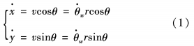
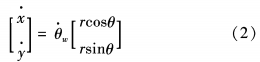
The velocity model is obtained from equation (1) :
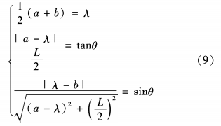
The force analysis diagram of the self-balancing robot is shown in Figure 1. In Figure 1, ○ is the center of the wheel shaft, P is the center of gravity of the fuselage, the body mass of the machine is ~ heavy force plus speed is g, the Angle of the machine axis is a, the distance of ultrasonic wave A directly to the ground is A, the distance of ultrasonic wave B directly to the ground is Lb, and the distance of the center of gravity from the platform under the fuselage is L. If the body tilts to one side with acceleration a, the optimal inertial force in the horizontal direction is:
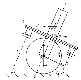
Figure 1. Force analysis diagram of self-balancing robot
2 double ultrasonic ranging control scheme
The self-balancing robot in this study uses two ultrasonic sensor modules to detect distance data. The HC-SR04 ultrasonic ranging module is selected, and the Arduino main control board obtains the Angle value a and Angle velocity of the current state of the fuselage after data fusion and conversion through first-order filtering, and then generates the corresponding PWM output value through PID parameter tuning. Form a "double ultrasonic ranging, positioning height comparison calculation, Angle value deviation calculation, correction data fusion, deviation adjustment - output control" self-balancing process.
2.1 Ultrasonic ranging principle and error adjustment
The distance measurement is completed by means of time difference ranging. The transmitting end of the ultrasonic sensor transmits the ultrasonic wave of specific frequency to the positive direction of the probe. The timer of the internal circuit starts to time when the ultrasonic wave is emitted. The timing diagram of ultrasonic emission and reverberation detection is shown in Figure 2.
The transmitting circuit will emit ultrasonic waves of specific frequency according to the pulse given, and the ultrasonic waves will be reflected back to the receiving end when they touch the interface of the measured object. Literature [9] adopts the method that the timer stops timing after the receiving probe of the ultrasonic sensor receives the reflected wave, and then obtains the time difference between the ultrasonic transmission and the receiving echo L. The propagation speed of the ultrasonic wave in the propagation medium is c(340 m/s in the air). Through calculation, the distance s between the TXD end and the measured interface is as follows:
Because of the high ultrasonic frequency, it can meet the measurement needs of various uses. But in low dimensional space, ultrasonic measurement will be affected by the surrounding temperature, self-response redundancy, slow echo, propagation medium and other factors. Ultrasonic waves propagate fastest in solids, followed by liquids, and slowest in gases. The characteristic speed of sound velocity c is related to the temperature of the propagating medium. In order to achieve accurate measurement of ultrasonic sensors, literature [9] proposes to set a temperature compensation circuit in the hardware to compensate for sound velocity errors caused by temperature changes. If the ambient temperature does not change significantly, you do not need to set temperature compensation.
For ultrasonic emission speed:
_1715909189390.png)
Formula T. =273.16℃, the temperature range of the normal operation of the temperature sensor is (-40~80℃) In this system, assuming constant, V0= 331.45m /s. Since the lag error of each receiver's wave head in the state is consistent with the hardware circuit delay, the transit time can be expressed as:

Due to the influence of ultrasonic measurement accuracy, literature [9] and literature [10] propose that what the timer really measures is not the time from TXD transmission to RXD receiving the echo, but the output time of a rising edge trigger level after the ultrasonic module has carried out temperature compensation. If the trigger point of ultrasonic module A is not triggered by the main control, but the trigger point of module B is triggered and emits ultrasonic wave, and the return signal is received by module A, or ultrasonic module A and ultrasonic module B are triggered at the same time, but both receive signals from each other, it will cause signal interference. In the next cycle, the TXD port sends out a high level pulse output at an uncertain period, thereby increasing the measurement error [10].
In view of this error, under the condition that the main electrical parameters of the ultrasonic sensor are satisfied, the system selects the HC-SR04 ultrasonic module with echo protection, and separates the ultrasonic module A and B as far as possible. The two-wheel structure also blocks the mutual interference of ultrasonic waves to a certain extent.
2. 2 Ultrasonic data fusion balancing algorithm
The change of Angle 0 in the polar coordinate plane of the robot is obtained by ultrasonic ranging to achieve the balance of the fuselage. When the two-wheeled robot is balanced, the following Angle value conversion formula should be met:
Where: L is the linear distance between the two ultrasonic modules A and B at the front and back of the fuselage; A is the balance point.
In the detection of self-balancing robot based on double ultrasonic waves, the sampling period is assumed to be 100ms, and the measured ultrasonic values A and 6 are obtained at time A:, combined with the predicted distance value at time (K-1). According to the predicted covariance S of the measurement, the measured value of time & is modified by filtering estimation, and then the distance of time (K+1) is predicted.
The balance Angle model obtained by ranging is shown in Figure 3.
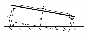
FIG. 3 Balance Angle model obtained from distance measurement
When estimating the motion state of the balanced attitude robot, the ultrasonic sensor coordinate of the robot adopts the polar coordinate system. Let the state vector E (k) of the system be:
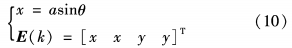
The state expression of system equilibrium is:

Since the sampling period of ultrasonic ranging is 300 ms, and the movement speed of the robot to maintain balance is relatively gentle, the adjustment process is set as approximately uniform movement in a local period of time, and the motion equation in the x direction is as follows:

Taking the mean of the velocity in the previous sampling period or the mean of the velocity in the first two state periods, we get:
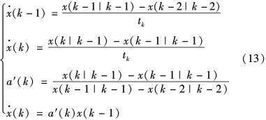
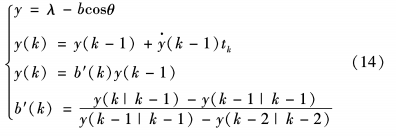
The equation of state of the equilibrium system can be obtained from equation (14) as follows:

The PWM output equation after PID data tuning is as follows:

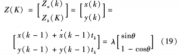
The balance drive system of dual ultrasonic robot based on Arduino realizes the balance of attitude after PID adjustment. The specific ultrasonic bidirectional ranging positioning balance model is shown in Figure 4. The measured value Z(k) obtained from the model diagram is:
FIG. 4 Bidirectional ranging positioning balance model
Since the errors of each state variable conform to the Gaussian distribution whose mean value is ○, the measurement equation under the equilibrium strategy is as follows:

Where: C is the characterization parameter of the measurement system, when the system is multiple measurement systems, C is the matrix; F0 is the noise error of the measuring system in the & state. From the measurement data of radial distance and deviation direction Angle of dual ultrasonic ranging in polar coordinates of the balance system, we can obtain:
The speed dial counts the PWM pulses generated by the motor encoder to monitor the displacement of the fuselage and the speed of the wheel. According to the ultrasonic sensor and attitude conversion, the motion attitude signal of the vehicle body is monitored. Through the dual ultrasonic data fusion process, literature [11] calculates the value of the output control voltage through relevant control algorithms, controls the two driving motors of the double ultrasonic wave, and then adjusts the traveling attitude and balance position of the vehicle body platform. Thus, the fuselage can maintain good movement coordination and balance [11,12].
2.3 Control scheme and marching strategy
Arduino has been used in various fields today. It is an open source control board using Atmel Atmega328 microprocessing controller. It has 0~13 digital Analog I/O and 0~5 Analog I/O, and the control effect is remarkable. The self-balancing robot uses an ultrasonic circuit Arduino as the core control module, the motor drive module is L298N, the motor is TT motor, and two HC-SR0.4 as ultrasonic ranging modules, powered by 7.4V / 2200mAh lithium batteries. Potentiometer is used for balancing point setting and PID debugging, facilitating data update and debugging, effectively reducing development time and production costs.
3 Test and simulation
The dual ultrasonic robot uses the main control Arduino, realizes the connection with the I/O interface with simple and fast programming, carries out the environment ranging positioning through the dual ultrasonic sensors, and uses the control algorithm to control the robot attitude balance. In the aspect of test verification, the echo detection data collected by ultrasonic wave is displayed through simulation. From the echo detection waveform received by the ultrasonic receiver, it can be seen that the attitude swing amplitude of the balanced system is not large, and it is basically around the equilibrium zero point, which has basic stability and data computability.
It is assumed that after complementary filtering, the Angle data converted by the two ultrasonic sensors is, the ultrasonic data collected is s, and the relative acceleration factor of the deviation Angle value converted by the ultrasonic sensor's distance measurement is L. The Angle data of the previous ultrasonic sensor after filtering is M2, and the fixed gain value selected is g. The filtered Angle data is realM, and finally the fused Angle data is obtained.
The experimental results show that the double ultrasonic self-balancing robot can keep balance effectively and move in balance under the control of balance algorithm. It can realize balanced retreat under traveling strategy and balanced turn under direction control with good stability effect.
4 Closing remarks
In order to realize the attitude balance and travel control of dual ultrasonic robot based on Arduino, a data fusion strategy of dual ultrasonic sensor is proposed. The experimental and simulation results show that the strategy is effective and feasible, and the dual ultrasonic self-balancing robot can maintain a good balance attitude, travel control and basic direction control are effective and reliable, and the balance stability and balance coordination are reflected. The overall hardware development cycle of this strategy is relatively short, the selection of materials is cost-effective, and can meet the requirements of reducing production costs under the premise of better control effect. In the following work, the attitude balance of multi-ultrasonic positioning self-balancing robot on uphill and downhill and uneven complex interface will be studied.
References:
[1] LIU Bin. Research on Software and Hardware Development of Two-wheel Self-balancing Car and Variable Structure Control Based on Fuzzy Linearization Model [D]. Xi 'an: Xidian University, 2009.
[2] Chen Wei, YAN Wenjie, ZHOU Chaoying, et al. Design of Control System for Two-wheel Self-Balancing Robot [J]. Sensors and Microsystems, 2008,27 (4) : 117-120.
[3] Yan Fei, Solemn, Wang Wei. Outdoor Scene Understanding of Mobile Robot Based on Multi-sensor Information Fusion [J]. Control Theory and Applications, 2011,28 (8) : 1093-1098.
[4] Su Zhiyi, Zhao Wei, Huang Songling. The status and important role of multi-sensor information fusion technology in modern measurement field [*1]. Electrical Measurement and Instrumentation, 2013,50(3): 1-5.
[5] Wang Hongbo. Application Research of Computers, 2013,30 (8) : 2252-2255, 2261 •
[6] Chen Hui, Deng Jicai, Wu Xiaohui, et al. Application of Multi-sensor Information Fusion in Motion Control of Wheeled Robot [J]. Journal of Sensing Technology, 2011,24 (6) : 915-918.
[7] Zhang Weimin, Duan Xiaoming, Zhao Yanhua. Research on Control of Two-wheel Self-Balancing Car [J]. Automation Technology and Application, 2011,30 (4): 10-13. (in Chinese)
[8] Sun Jianqin, He Yajing, Meng Xiangzhong. Research on Optimal Fuzzy Control of Two-wheel Unbalanced Car [J] • Computer Simulation, 2011, 28(2):184-186,406.
[9] ZHANG Jian, WANG Wei, HE Junfeng, et al. Novel Positioning Method Based on Double Ultrasonic Module [J]. Sensors and Microsystems, 2012,31 (9) : 22-24,31.
[10] Jiang Lin, Yan Jihong, Zang Xizhe, et al. A new ultrasonic absolute positioning method [J]. Journal of Jilin University (Engineering and Technology Edition), 2019,39(1) : 188-193.
[11] CAI Jianxian, RuAN Xiaogang. 0CPA bionic Autonomous Learning System and its Application to Robot Attitude Balance Control [J]. Journal of Modeling and Human Intelligence, 2012, 4 (1), 138-146.
[12] Zhu Xiaozhou, Li Yubo, Lu Huimin, et al. Overview of Vision-based mobile robot passable Area Identification [>!] Research on Donkey Use in Computing, 2012,28(6):1135-1137.
[13] Ruan Xiaogang, CAI Jianxian, Chen Jing. Self-balancing Control of two-wheeled robot based on reinforcement Learning Rules [J]. Computer Measurement and Control, 2009, 17 (2) : 321-323. (in Chinese)