


The automotive anti-collision system based on Ultrasonic
0 Introduction
With the development of city economy and the increase in population, as of 2013 ,the national vehicle retains the quantity to 137 million, nearly an average annual increased more than 11 million cars in the past decade, however, the rate of mortality caused by traffic has increased meanwhile. In recent years,the traffic accidentshappen frequently,which directly threats the public safety and causes huge loss of property. The cause of the serious situationas follows : speeding or drunk driving and the uselessness of the system of automobile anticollision.With the development of the embedded technology and related hardware, the embedded vehicle monitoring system starts to enter the automotive industry at the same time. Internationally,such as Germany, Japan,the United States and other counties of advanced car producers began to research and develop the safe mechanism of active anti-collision more than a decade ago. January 6 ,2014, TOYOTA and Audi showed independent researches and developments of unmanned vehicles in the United States. The research on automotive anti-collision system technology is relatively rare. There are two companies,Tai Yuan and Chao Yue,which research and develop the management system. The automotive anti-collision device of Tai Yuan,is the most advanced products in China at present. Its technical content has been at the top of the worldrs advanced technology, but the cost is expensive. According to the above situation,this article optimizes the vehicle model based on the ultrasonic ranging system in a wide ra n g e B y the ARM development platform,a system of vehicle anticollision is designed,which is suitable for modem vehicle. The function of the system is simple and practical,the price is reasonable, and the system has the advantage of universal.
1 System hardware design
In this paper, we choose a kind of embedded system based on ARM processor^4^ ,and build the necessary peripheral equipment, with the ARM 11 processor as CPU combined with ultrasonic distance measurement device,speed sensor,alarming device and related device interface. A typical embedded devices is built. The system uses the mainstream Linux operating system. The framework of the overall design of the system is shown in Fig.l.
1.1 ARM master controller
OK6410 development board based on Samsung ARM 11 processor, which is a RSIC processor with low power consumption and high performance. It is based on ARM 11 kernel ( ARM1176JZF-S) and can be widely used in mobile phones, general processing and other fields. S3C6410 2. 5G and 3G communication service provides optimized hardware performance and built-in powerful hardware accelerators, including motion video processing,audio processing,2D acceleration,display and scaling and so on.
1.2 Ultrasonic distance measuring device
In the study of the system of automotive anti-collision, for distance measuring device, radar, laser, ultrasound and others are commonly used. The performance comparison is shown in Table 1. Millimeter wave radar is most widely favored, but its high price is not conducive to be spread. Laser radar and high-precision camera are greatly affected by the environment, so the development of ultrasonic anti-collision system with a large range of applied intelligent vehicle systems is necessary. Ultrasonic Ranging,from the principle, can be divided into two : resonance type and pulse reflection type. Since functional requirements, we use pulse reflection, namely use the ultrasound reflection characteristics in this system. At room temperature environment, we usually take the ultrasonic speed of 340 m /s. the distance from the obstacle emitting.
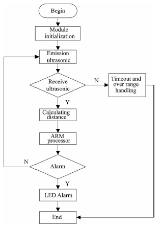
Figure 1 System overall design block diagram
![]()
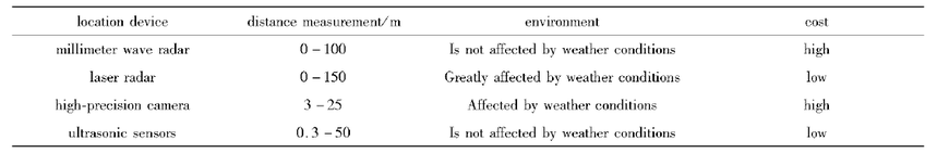
Table 1 Comparison of different location device
1.2.1 Ultrasonic transmitter module
Ultrasonic transmission circuit includes two parts : ultrasonic control circuit and ultrasonic wave generating circuit. We choose DY150 high-power transducer as ultrasonic probe model, and the central frequency of the transducer is 15 kHz,maximum range is 50 meters. Its biggest characteristic is to transmit and receive integrated together.
1.2.2 Ultrasonic receiver module
This article adopts the way of interrupt signals to receive the signal. Ultrasonic sensor reflects a bunch of ultrasonic signal which spread through the air,and return when it encounters some obstacles. Ultrasonic receiving device receives the echo signal. Due to the amplitude of received echo signal is small,it will be further processed by amplification,detection and filtering. Finally,a pulse signal is output through a voltage comparator, and then is input to the MCU external interrupt input end,causing SCM interrupt.
1.3 Alarming Module Design
In the vehicle driving process, if the distance between two vehicles is less than the safe distance, the alarming module of the ARM development board is used to light the LED alarming circuit with the anti-collision algorithm.
2 Establishment of automobile anti-collision models
2.1 Principle of establishing model
In order to make the system be able to effectively serve as warning to the driver and be unable to interfere with the driver for normal driving by too many reminders, the establishment of model should follow .
1) The distance of reminder and alarm should be left for enough reactive time to the driver. When the driver hears the alarm,he can prepare to decelerate following the normal habits.
2) The danger alarming distance (emergency braking critical distance) is set up without consideration of the driverrs reactive time and the preparative time. When the driver is alarmed, he has been ready to brake. Secondly, it should prevent frequent warning from disturbing the normal operation of the driver.
3 ) The model should be able to reflect the most dangerous situation of cars under different motion state, and has good robustness to judge the dangerous distance underdifferent conditions.
2.2 Overview of automotive collision model
In order to ensure driving safety, the car which is at high speed on the highway must keep a certain distance S from the front vehicle. The anti-collision system based on the size of the distance between the two vehicles is divided into three stages:namely remind distance St,alarming distance Sw,and forced braking distance Sd. In the same situation the expressions are as follows :5t > 5W > Sd. When the distance between test car and the car in front is in remind distance St, the range finder will issue a warning signal to remind the driver that the distance between two vehicles is too short. At this time the driver has enough reactive time to hear the reminding calm and be ready to slow down according to normal habits. When the distance between test car and the car in front is within reminding alert distance Sw, there is a risk factor of two vehicles, which is relatively low. After hearing the alarm,the driver should be vigilant and pay attention to the situation of the front car to
ensure the safety of driving. When the distance between test car and the car in front is in alert distance Sd, the risk factor is high,and the driver has no enough time to make a judgment. The system will exceed the driver,
because the vehicle will be forced to send a deceleration signal and decrease the carrs speed to increase the distance between two cars,which reduces the driving risk factor.
2. 2. 1 The oretical analysis of braking distance
In order to determine St,Sw,Sd,the specific values of three kinds of distance in the braking model, we need to analyze the condition of two vehicles during braking, through calculation the distance needed in the process of braking to determine the collision risk. For car in the actual car braking process,in case of the tire does not lock up,the braking resistance comes from the friction between the tire and the ground,and the friction depends on the friction coefficient. From energy conservation we can get power of friction force on the body which is equal to the variation of the kinetic energy of the object:yLtiV5 = 1/2 mv2,where N is the number of cars on the ground p re ssu re is the ground friction coefficient for car,S is the braking distance,i is the mass of the car,i; is the speed of the car,and the pressure of car to the ground is equal to the gravity of the car F = mg that we get mg/xs = l/2mv2 ,namely s - v 2/{2fjig).
The common accident on the highway happens since the speed of the car behind is higher than the car front. In this condition the distance between the two cars is too short with a greater risk. Assuming there are twocars on the coincide road, the car behind is A ,the speed of A is va ,the car front is B,the speed of B is vhyva >i;b,and the distance between two cars is S. The braking distance of the two carsis as follows:
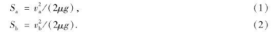
If S is greater than Sa, in this case, even if the vehicle in front instantaneously stops due to the occurrence of an accident,the car behind also has enough distance to brake until stop. So we consider the distance between the two cars,and the risk coefficient is

If driver B found an accident in front of him,and he has enough distance to brake the car until stop,the braking distance of the car is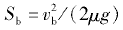 , assuming that the two cars distance is 5a - 5b ,to make sure the safety, the car behind should completely brake. At this time,the accident probability is very high,we now set the risk coefficient as 1, where

2. 2. 2 Numerical value determination
Anti-collision system not only must remind the driver in relatively safe distance between vehicles, but also canrt send a wrong braking signal,which can affect the normal driving,so we can reference the increase of risk to determine the set.
2. 2. 2. 1 The setting of St
There is Maintain Safe Distance principle in the safe driving knowledge that people should maintain a distance for one over one thousand of the driving speed. For example,the carrs speed is 50 km/h,we should keep the 50 m distance,and the speed is 120 km/h,we should keep the distance 120 m. We will base on the basic driving knowledge to set the remind distance as St =Vt
2. 2. 2. 2 The setting of SW
It will alarm as long as there is a dangerous situation. The alarming distance is the distance when the risk factor is 0 ,where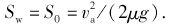
2. 2. 2. 3 The setting of Sd
It will be dangerous,if the driver does not make the braking measure. We will put the risk factor of 0. 5 for safety reasons,so we set 5d as the distance between S0 and S1,where Sd = (S0 + S1 )/2.
2. 2. 3 Perfection and verification of the model
2.2.3. 1 Delay consideration
2. 2. 3. 2 Velocity difference coefficient
2. 2. 3. 3 Friction factor
2.3 Final braking model
After the perfection of the model,we can locate the three deceleration phases
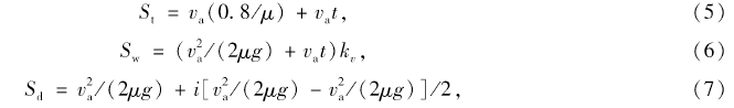
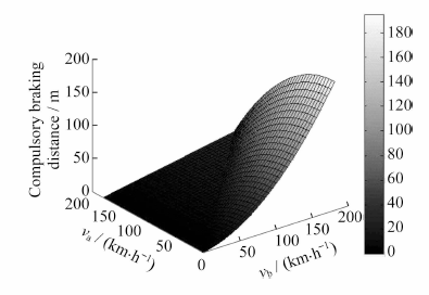
Figure 3 Three-dimensional m a p of the braking distance
3 System software design
The program consists of a main program and Ultrasonic Ranging proceduresT he main program is to complete the system initialization, load anti-collision algorithm and set LED alarm. Ultrasonic distance measuremeiu program is lu uumpieie uie uausmissiuii aim reception of ultrasonic wave and obtain the distance between the ultrasonic transmitter and the obstacle. AVR microcontroller and ARM development board transmits data through Universal Synchronous/Asynchronous Receiver/
Transmitter ( USART). Program flow chart is shown in Fig. 4.
3.1 Main program design
Firstly,0k6410 development board implement module performs initialization, including a LED driver initialization and serial receiving procedures, through the way of interrupting to receive ultrasonic range data which is sent by AVR microcontroller. Thus the data are substituted into the alarming algorithm as alarming information, then the information is written to the LED driver to complete alarm.
3.2 Ultrasonic ranging program
The ultrasonic launch program initializes the initial parameter , and then sends the 15 kHz ultrasonic pulse signalper 60 ms. By comparison with the timer,the time of delay of sending ultrasonic signalis 50 ms. So we enable the interruption and initialize the timer to wait for the signal. Only when the echo is received, the waiting program is shut, the interruption is off and the timer starts to count. Otherwise, the waiting program continues. According to the difference between the read echo and the transmitted wave, the distance is calculated every Is. The actual measurement results are shown in Table 2.
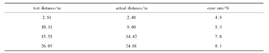
Table 2 Actual measurement result
In this paper, the ultrasonic distance measurement device obtains travel distance between vehicles and calculates the speed information about the front vehicle, then using the computer to simulate the speed of the current car. The distance from the two vehicles that will speed the automotive anti-collision warning information were substituted into the model. System design is mainly dominated by the ultrasonic ranging. It calculates the traffic data by the analysis of theory and practice and ARM processor. At the same time, it uses LED light to send alarming information for the automobile anti-collision. With the improvement of the system,it will be used more widely.
References :
[ 1 ] Zeng Y. Research on automotive anti-collision warning system based on ARM + FMCW radar [ D ] . Guangzhou :South China University of Technology,2011.
[ 2 ] Pi W B. Research on automobile anti-collision system based on AR M [ D ] . Wuhan : Wuhan University of Technology, 2009.
[ 3 ] Pan Z M. A large range of ultrasonic distance measurement system [ D ] . B e ijin g :National University of Defense Technology, 2006.
[ 4 ] Tai Y N ,H u G ,C hen X P. Based on AR M embedded vehicle monitoring terminal design and implementation [ J ] . Computer Measurement and C o ntrol,2008,1 6 (8 ) ;1125 -1 1 2 6 ,1 1 4 0 .
[ 5 ] Zhao X C. Key techniques research on radio frequency of high precision radar ranging system [ D ] . N an jin g:Nanjing U n iversity of Science and Technology ,2014.
[ 6 ] L i C D. Anembedded system key technology analysis and the development and application [ J ] . Heilongjiang Science, 2 0 1 4 (2 ) ;30 - 3 1 .
[ 7 ] Huang M Z. Research of steaming media transmission system based on 3G [ D ] . Guangzhou : Guangdong University of Technology ,2013.