


The automatic control system of farm machinery based on ultrasonic distance measurement
As a key technology of precision agriculture, agricultural machinery autonomous walking in the field can greatly reduce the labor intensity of operators and adapt to the development trend of modern fine agriculture production.
The path planning of agricultural machinery platform has been studied both at home and abroad, and has been widely used in agricultural machinery rotary tillage and seeding, field fertilization, plant protection spraying, crop harvesting, etc. [2]. yoshisda et al. in Japan adopted GPS and FOG fusion technology and developed PID algorithm to control automatic driving of agricultural machinery by taking PH-69 rice transplanter as a prototype [3]. Zhou Jun et al. studied the path tracking of agricultural robots through machine vision and designed the machine vision navigation control system based on wheeled agricultural robots.
The research of agricultural machinery navigation and positioning is based on a variety of methods, such as GPS navigation, dual laser radar positioning, machine vision tracking, multi-sensor fusion position detection, etc. But currently available farm machines tend to be large, and such large farm machines are usually equipped with GPS and are only suitable for operation on large farms. But field work is often still done by foot. At present, the research on autonomous walking in small space mainly focuses on intelligent inspection robots and electric intelligent vehicles, while there are few researches on agricultural machinery driving in complex and changeable lines. Now the combination of agricultural machinery and actual agricultural art, aiming at the defects of agricultural machinery in agricultural production, the design of small agricultural machinery row to row self-walking control system has a strong practical application value.
1. Kinematic model of crawler agricultural machinery
The control strategy of self-walking between rows and the position adjustment of agricultural machinery need to be based on the kinematic model of tracked agricultural machinery [5]. Figure 1 shows the crawler agricultural machinery kinematic model. The global ground coordinate system XOY and the agricultural machinery vehicle body coordinate system xoy are established respectively. The agricultural machinery vehicle body coordinate system is located at the center of the agricultural machinery vehicle body. The direction of y axis is the forward direction of agricultural machinery. When agricultural machinery is turning in progress, it takes a point in the plane as its instantaneous center of rotation, which is denoted as point Q. The connecting distance from the central point o to point Q of agricultural machinery is the steering half-diameter R, and the speed of agricultural machinery rotating around point Q is the steering angular velocity ω.
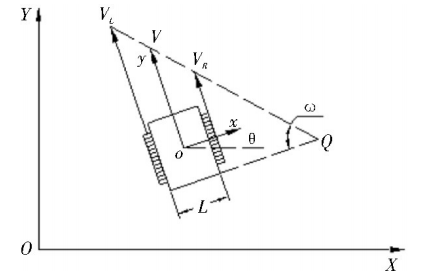
Figure 1. Kinematic model of crawler agricultural machinery
The following assumptions are made for the kinematic model of crawler agricultural machinery: (1) The agricultural machinery is always moving on the plane and the resistance coefficient is fixed; (2) there is no slippage on both sides of the track at uniform low speed steering; (3) The tracks on both sides are identical and do not affect the trajectory; (4) The center point o of agricultural machinery is regarded as the actual center of mass of agricultural machinery; (5) The influence of centrifugal force and steering angular velocity ω is ignored in the steering of tracked agricultural machinery [6]. When Q is the instantaneous center of rotation of agricultural machinery and R is the steering radius, the relationship between the speed of driving wheels on both sides, the speed of track on both sides, the running speed of agricultural machinery, the angular steering speed and the steering radius is shown in formula (1) - (5).
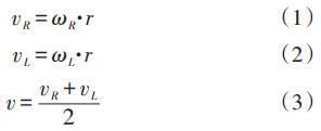
Where, ωR and ωL are the angular velocity of the left and right driving wheels respectively; r is the radius of the driving wheels; vR and vL are the traveling speed of the tracks on the left and right sides respectively; ωis the angular velocity of the agricultural machinery around point Q; v is the linear velocity of the center point o of the tracked agricultural machinery body; L is the width of the agricultural machinery body; R is the steering radius of the agricultural machinery body. Different driving states of agricultural machinery are analyzed. When vR and vL are equal, that is, when the agricultural machinery is running in a straight line, the turning radius is regarded as infinity. When vR and vL are equal in magnitude and opposite in direction, that is, the agricultural machinery is in a differential steering state in place, the steering radius is zero, and the instantaneous center point Q is coincident with the central point o of the agricultural machinery. When vR and vL are not equal, the agricultural machinery rotates around the instantaneous center point Q and uses any R as the steering radius for steering [7].
When the steering angular velocity of agricultural machinery is ω, the arc length of agricultural machinery movement in Δt time is denoted as E. The arc length of agricultural machinery movement is converted into the Angle n of agricultural machinery movement in Δt time by using the arc length Angle formula. The relationship between the arc length of agricultural machinery movement and the running speed of the left and right crawler can be expressed as formula (6) - (7) :

At present, there are three differential steering modes for tracked vehicles [8]. In this paper, independent steering is selected, which requires less power than center differential steering and outside accelerated steering. The principle is that in the process of agricultural machinery steering, the track speed near the rotating instantaneous center point Q decreases, while the track speed far away from the rotating instantaneous center point Q remains unchanged.
2. Vehicle position detection strategy
At present, non-contact distance sensors are widely used, including laser ranging, infrared ranging, ultrasonic ranging; The infrared ranging sensor is easy to be affected by light intensity, and the range is small, easy to be disturbed in the complex field environment; Laser ranging has high precision but complex structure and high cost, which is suitable for intelligent inspection robots with high precision operation. Ultrasonic ranging has good directivity, strong penetration, and strong waterproof and antifouling performance of ultrasonic sensors, which can still maintain a better level in complex operating environments [9-11].
When agricultural machinery is operating in the field, the signal transmitted by the sensor is often affected by the installation position, the noise of agricultural machinery itself or the change of environmental factors. There is a large error in the output distance signal of ultrasonic sensor. It is necessary to pre-compensate the distance signal measured by ultra-acoustic wave to ensure that the output distance signal of ultrasonic wave sensor is closer to the actual distance. Ultrasonic distance signal is processed based on relative error least square method.
According to the mathematical theorem of least square fitting [12], the ultrasonic measured value is different from the actual value, the relative error is selected for fitting calculation, and the linear relationship between the distance measured value and the actual value is expressed as follows:
The relative error of measurement is expressed by the least square formula as follows, where n is the sampling times of the measured distance value. Two groups of corresponding data are taken from the measured value to establish a system of equations to obtain the values of M and N:
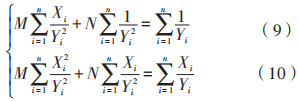
Due to the principle of ultrasonic sensor echo ranging, that is, there is a measurement dead zone of ultrasonic sensor, the measurement dead zone of ultrasonic sensor is measured from 0 to 26 cm by the experiment, so the ultrasonic ranging experiment selected between 27 cm and 50 cm sampling. Experimental ranging results are shown in Table 1.
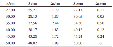
The measured distance value and the actual value in the table are substituted into the fitting formula (9) and (10), and M=1.077 0 and N=-4.070 8 are obtained. Then the relationship between the actual distance value and the ultrasonic measured distance value is fitted according to Equation (11) :

By comparing the relative error values before and after least square fitting in Table 1, the accuracy and stability of ultrasonic measurement values after processing have been significantly improved.
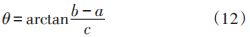
The sensor is used to detect the distance between the right front side, left front side, right rear side and left rear side of the car, and the distance between the ultrasonic installation position and the outermost part of the car body should be greater than the ultrasonic measurement dead zone, so as to ensure that the ultrasonic works within the normal ranging range. FIG. 2 shows the schematic diagram of analyzing and calculating the deviation of course Angle of agricultural machinery by ultrasonic distance measurement.
In FIG. 2, a is the distance value measured on the left front side of the vehicle body, b is the distance value measured on the left rear side, c is the length of the agricultural machinery, and θ is the included Angle between the y axis of the coordinate system of the agricultural machinery body and the Y axis of the global ground coordinate system, namely, the deviation value of the heading Angle of the agricultural machinery when it runs in a straight line between the lines. According to the trapezoidal geometric relation, the relation formula between the two is obtained, as shown in Equation (12) :
As shown in Figure 3, the linear distance between the central position of the vehicle body and the planting rows of crops on both sides is the distance d1 between the agricultural machinery and crops on both sides. When the agricultural machinery normally runs on the center line between rows, there is a geometric correlation: a=b=d1. When the agricultural machinery has course Angle deviation and position deviation, according to the geometric relation:
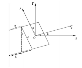
FIG. 2 Schematic diagram of course Angle deviation calculation
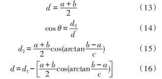
In Formula (16), when the measured values of the four ultrasonic sensors at the front and rear of the car body are used to calculate the agricultural machinery operation, the car body heading Angle deviation θ and the car body position deviation d relative to the center line between the lines are taken as the input of the fuzzy control algorithm below.
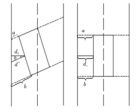
FIG. 3 Schematic diagram of position deviation calculation
3. Automatic fuzzy control strategy
Fuzzy control method uses the basic thought and theory of fuzzy mathematics to analyze the system under complex and changeable environment, the variables are often difficult to be described by traditional control theory. Therefore, fuzzy control theory is introduced to simplify the dynamic analysis and control of the system. It can emulate the experience and strategy of experts in this field, and the intelligent decision-making ability is far beyond the traditional control theory. A paste controller usually includes fuzzification, fuzzy decision making, and unfuzzification [13-14].
The relationship between course Angle deviation θ, position deviation d and the position of the interrow centerline is roughly as shown in Figure 4. It is stipulated that when the position deviation of car body is on the left side of the center line between rows, the position deviation d is negative. When the position deviation of car body is on the right side of the center line between rows, the position deviation d is positive. When the heading direction refers to the left front, the heading Angle deviation θ is negative; When the heading direction points right ahead, the deviation θ is positive. FIG. 4 (a) indicates that the position deviation is negative and the course Angle deviation is 0; FIG. 4 (e) indicates that the position deviation is 0 and the heading Angle deviation is negative. Figure 4 (i) shows that the position deviation is positive and the heading Angle deviation is positive.
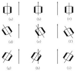
FIG. 4 Schematic diagram of course Angle deviation and position deviation
The establishment of fuzzy control rules is based on the manual operation experience of agricultural machinery, and its establishment rules should conform to the actual operation mode: when the vehicle body positioning deviation d, course Angle deviation θ and the center line deviation between rows are large, the direction should be adjusted as soon as possible to prevent the agricultural machinery from driving into crops on both sides; When the car body positioning deviation d, course Angle deviation θ and the centerline deviation between rows are small, both the elimination of deviation and the stability of agricultural machinery should be dealt with. The output parameter of the fuzzy controller is agricultural machinery steering Angle n, and Equation (17) is the fuzzy relation of the three:
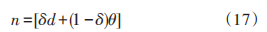
Where, δ is the correction factor of the fuzzy controller, and the emphasis on eliminating position deviation and course Angle deviation is different. For agricultural machinery running between lines, more attention should be paid to the correction of position deviation, so the value of δ should be appropriately increased.
The fuzzy control system is a double input and single output fuzzy controller. According to the experience of relevant experts in the control process, the input and output are quantified and 7×7 fuzzy language rules are summarized. The fuzzy control rules are shown in Table 2:
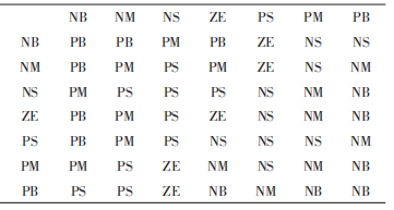
According to the established fuzzy control rule table, the fuzzy set of position deviation, course Angle deviation and steering Angle of three variables in this system is {negative large, negative medium, negative small, zero, positive small, middle, large}={NB,NM, NS,ZE,PS,PM,PB}. The Gauss membership function of steering Angle n is shown in Figure 5.
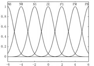
Figure 5. n membership function of steering Angle
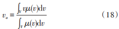
The area center of gravity method is used to de-blur. The area center of gravity method is the center of gravity of the area surrounded by the curve of membership degree function and the horizontal coordinate, which is used as the final output value of the paste reasoning. Compared with other methods of de-fuzzification, the area center of gravity method has smoother output reasoning control. The output changes in response to even small changes in the input signal. Its mathematical expression is shown in Equation (18) :
When the position deviation d=-6 and the heading Angle deviation θ=-6°, the steering Angle n=5.09°. After quantizing the basic domain, adjusting course Angle deviation and position deviation within the range [-6,6] can be obtained by fuzzy reasoning.
4. Motion simulation of self-propelled control system
Matlab was used to simulate and verify the automatic fuzzy control algorithm between lines of agricultural machinery. During the simulation, the first quadrant Angle bisecter of y=x was set as the center line of automatic walking between lines, that is, the predetermined driving path. The initial position of the simulation was set at (0,0), and the part y>x was set as the left side of the center line of the lines, y
In FIG. 6, (a) - (c) is the motion simulation simulation of agricultural machinery body position deviation d and course Angle deviation θ under several typical values.
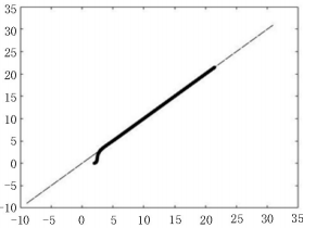
FIG. 6 Simulation of self-propelled movement between rows of agricultural machinery
Combined with the fuzzy function expression of equation (17), it can be seen that the self-moving strategy between rows of agricultural machinery is mainly to eliminate the position deviation of agricultural machinery body, and the appropriate choice of δ value is large. When the position deviation and heading Angle deviation are both positive NB or negative PB, the agricultural machinery needs to adjust the position of the body between the lines quickly. In this case, the electric agricultural machinery needs a large steering Angle n. According to the model and formula established in this paper, the track speed difference between the left and right sides of the agricultural machinery increases to provide a larger steering Angle for the agricultural machinery. When the position deviation is at positive small NS or negative small PS but the course Angle deviation is at high NB or negative large PB, agricultural machinery does not need too much body position adjustment at this time, only need to correct the course Angle deviation in time. When the deviation of agricultural machinery direction Angle is zero ZE but there is position deviation, the position of agricultural machinery body should be adjusted in time.
5 Hardware design of self-propelled control system
The self-propelled control system designed is installed in small electric crawler agricultural machinery so as to better combine agricultural machinery with agricultural art. Currently, wide-narrow row planting technology is adopted for most crops in China [15], and the narrow row width of most crops planted in wide-narrow row is generally within 35~50 cm, which is not suitable for walking in narrow row. The width of the wide rows is generally between 90 and 130cm according to the different agricultural crops. The selected agricultural machinery is 160 cm long, 66cm wide and 45cm high. The rubber track is more suitable for driving in complex field environment.
The agricultural machine is powered by 48 V/800 W brushless DC motor. Compared with the traditional fuel engine drive, the brushless DC motor has a relatively closed structure and is suitable for use in harsh environment such as farmland. Its rated current is 20 A, torque is 5 N·m and speed is 25 r/s. Force generated by a single motor is calculated according to the torque formula of Equation (19) :

The shaft diameter of the DC motor is about 0.008m, then the moment arm is the radius of the shaft of the motor is 0.008/2= 0.004m. According to Equation (19), the force generated by a single motor is about 1 250 N, and the gravity coefficient can be calculated as follows: 1 250 N/(9.8 N/ kg)≈128 kg, the whole weight of the agricultural machinery to bear the load is about 250 kg.
Electric farm machinery uses 58.2Ah lead-acid battery as power source. The output power of the motor is calculated as shown in Equation (20) :
Formula (21) is the battery discharge, where FAH is the battery discharge time, ZL is the battery discharge current value, NAH is the battery capacity, 0.85 is the battery discharge efficiency. Combined with Formula (21), the maximum driving distance of farm machinery in field operation is about 7.5km:
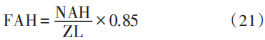
Figure 7 shows the circuit diagram of the ultrasonic body detection system. The ultrasonic sensor is DJLK-003 transceive-receiving integrated ultrasonic module, flat small Angle ranging, working temperature range is -15~+60 ℃, the probe is equipped with a certain dust-proof and waterproof grade, suitable for wet and harsh measuring environment. The body position distance value is sent through the RS485 protocol. The RS485 bus has strong resistance to common-mode interference and the maximum data transmission rate can reach 10Mbps. Four groups of distance values can be collected at the same time if different slave addresses are set.
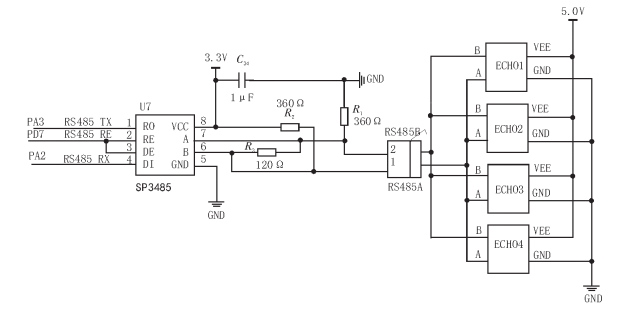
Figure 7. Circuit diagram of ultrasonic body detection system
The self-drive control system of the agricultural machinery through STM32 chip to calculate the distance value of the agricultural machinery body and then send the speed regulation voltage to the motor driver. As can be seen from the above, the differential steering mode of agricultural machinery is independent differential steering, so it is subtracted from the forward voltage signal through the subtraction circuit. During the interline operation, the constant value of 0-5.0V speed regulating voltage is continuously output to the motor driver on both sides by the speed regulating knob circuit. When the driving position of agricultural machinery deviates from the center line between rows, the main control chip receives the measured values of four groups of ultrasonic sensors, takes the position deviation and heading Angle deviation as input, outputs the steering Angle of agricultural machinery through fuzzy calculation, and then converts the steering Angle of agricultural machinery from -30° to 30° into the speed difference of left and right tracks according to the steering model. The voltage value of 0~ 2.4V is output through the D/A of STM32, which is subtracted from the output voltage value of the speed-regulating knob circuit to the motor driver near the center of the turning moment, and the speed of the unilateral track is reduced. The schematic diagram of its circuit is shown in Figure 8.
FIG. 8. Circuit diagram of the self-propelled control system between lines
As shown in FIG. 9, the Multisim14.0 circuit simulation of the self-walking control system between agricultural machinery lines was carried out. The speed regulating knob circuit used a 10 kΩ partial pressure rheostatic to output 0~5V adjustable voltage signal to the motor driver to control the forward speed of the self-walking between agricultural machinery lines. The DAC of STM32 is in voltage output mode, which can be directly used as signal source. Two 10kΩ partial pressure rheostat are used to simulate dual-channel DAC to output 0-2.4V differential steering voltage signal. When the control chip determines that the agricultural machinery needs to turn to correct the forward direction through calculation, PA4 or PA5 outputs an electrical voltage signal corresponding to the turning Angle. After passing the voltage following circuit of the preceding stage, the straight voltage signal output from the speed regulating knob circuit is subtracted by the voltage subtraction circuit of LM358N. Then the voltage signal is output to the motor driver through the secondary voltage following circuit. The left and right sides of the motor driver form the voltage difference according to the difference of double D/A output; The driving voltage of the motor driver on one side is reduced, and the driving voltage of the motor driver on the other side is unchanged, that is, the speed of the near rotation center side is reduced, the speed of the far rotation center side is unchanged, and the body deviation is corrected by agricultural machinery. In the simulation, PA5 controls the left turn and PA4 controls the right turn. The speed regulating knob continuously outputs 3.0V voltage signals to simulate the forward speed of agricultural machinery. When the DAC at PA5 generates 1.2V analog voltage signals, 1.8V and 2.97V voltage signals are sent to the motor drivers on both sides, and the motor speed on the left side decreases. The speed of the motor on the right is unchanged, and the driving route of agricultural machinery is corrected to the left [16].
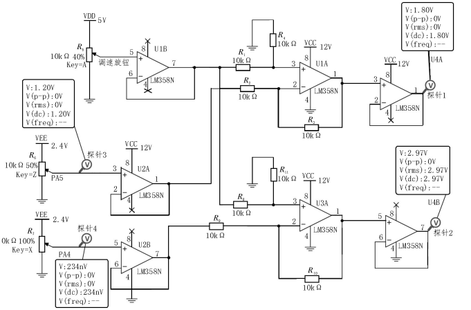
Figure 9 Circuit simulation diagram of Multisim14.0
6. Test and analysis
After the simulation test of the fuzzy control strategy and the circuit of the self-propelled control system respectively, the field test of agricultural machinery is carried out. The experimental field of daylily planting experimental base in Yunzhou District, Datong City, Shanxi Province was selected for the experiment, and its wide row width was about 1.3m. As a kind of economical crop, the picking process of yellow cauliflower is complicated, which requires workers to walk between the rows to pick.
Through the research on artificial daylily picking operation, the optimal speed of agricultural machinery is about 0.83 m/s. At this speed, agricultural machinery can pick the daylily with a distance of 500m in a single trip, which takes about 10 min. Therefore, it can finish the four-row daylily picking for two people in 20min, with an efficiency of about 5min/ row. Compared with manual walking picking, two people can pick 4 rows of daylily at the same time, but the walking speed of manual picking is about 0.3m/s, so in the manual walking picking mode, the picking operation with a distance of 500m in a single trip takes 30 min, and its efficiency is about 7.5 min/ row. According to the experiment, the efficiency of picking daylilies is improved by about 30% when agricultural machinery is used to walk between rows. The use of small electric agricultural machinery will not cause great damage to crops and land, but also greatly reduce the labor pressure of farmers and optimize their working conditions [17].
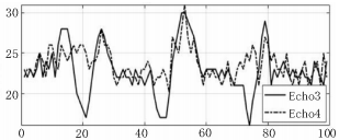
Figure 10 and 11 show the distance sampling values of the four sensors during a single daylily picking operation, in which Echo1, Echo2, Echo3 and Echo4 are the distance sampling values of the left front, left rear, right front and right rear ultrasonic sensors respectively. FIG. 12 shows the curves of the left speed regulating voltage Vleft and the right speed regulating voltage Vright transmitted to the motor driver. When the position deviation and heading Angle deviation are both large, the agricultural machinery will correct the path, and the variation range of speed regulation voltage is also large, so as to facilitate quick correction. When the range of distance sampling value is not large, the default is the interference of complex operating environmental factors between lines. The test results show that the position of agricultural machinery is basically located in the center line of the row in the 500m operation test without intervention.
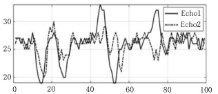
FIG. 10 Distance sampling values of the left front and rear sensors
7 Conclusion
In this paper, the strategy of self-walking between rows of electric agricultural machinery based on ultrasonic distance measurement is designed to optimize the picking mode of artificial agricultural production such as daylilies picking. The intelligent agricultural machinery greatly reduces the labor intensity of agricultural producers. The distance sensor and microcontroller are used to judge and correct the driving attitude of agricultural machinery between rows in real time. Even in the real machine test under the complex and changeable field environment, the agricultural machinery can drive along the road between rows without the need of human driving intervention, which solves the current situation that agricultural production can only rely on human when large agricultural machinery cannot enter the field operation. In the future, the agricultural machine can be modified in a variety of ways, so that it can undertake crop picking, inter-line manned and agricultural product transportation, inter-line plant protection spraying and other tasks.
References:
[1] Luo Xiwen, Liao Juan, Hu Lian, et al. Research progress of intelligent agricultural machinery and practice of unmanned farm in China [J]. Journal of South China Agricultural University,2021 (6):1-15.
[2] Yang Hongwei, Su Renzhong, Xie Xiaoqin. Design and implementation of Operation detection System for agricultural automatic driving Equipment [J]. Hebei Industrial Science and Technology,2021, 38(4):280-285.
[3] Yao Lintao, Luo Xiang, Cao Xiaolin, et al. Intelligent Micro-cultivator navigation System based on RTK-GPS [J]. Journal of Agricultural Mechanization Research,2021,43(9):78-82.
[4] Zhou Jun, Hu Chen. Interrow positioning Method of Robot in close planting orchards [J]. Transactions of the Chinese Society for Agricultural Machinery,2015,46(11):22-28.
[5] Guan Zhuohuai, Mu Senlin, Wu Chongyou, et al. Analysis and Experiment on Steering Kinematics of crawler Combine in Paddy Field [J]. Transactions of the Chinese Society of Agricultural Engineering, 20,36(13):29-38.
[6] Liu Wenxue, Wang Tao, Zhou Yingchun, et al. Experimental research on Motion Control of tracked armored Vehicles in Virtual Reality [J]. Journal of Ordnance Equipment Engineering, 2019,40(9):135-139. (in Chinese)
[7] Sun Jingbin, Chu Ping, Pan Guanting, et al. Design and Performance Test of Remote Control Omni-directional Flat Mountain track Tractor [J]. Transactions of the Chinese Society for Agricultural Machinery, 2021,52(5):358-369.
[8] Li Hui, Jia Wenfei. Research on Steering Form and Characteristics of Construction Machinery Vehicle [J]. Times Agricultural Machinery,20,47(3):85-86.
[9] Hu Youbing. Design of Conveying belt coal flow detection System based on laser ranging sensor [J]. Mining and Processing Equipment,2021,49(9):35-38.
[10] Lei Daozhong. Design of Ultrasonic Sensor Intelligent Arena Counterrobot based on Microcontroller [J]. Information Technology and Informatization,2021(8): 218-220. (in Chinese)
[11] Yang Fan, Reddy. Obstacle Avoidance Car based on STM32 Design [J]. Manufacturing Automation,2021,43(3):40-43.
[12] Wang Zhaowen, Yao Yi, Tang Biying, et al. Research on Temperature drift Compensation of Electrochemical Sensor based on least square Method [J]. Industrial Instrumentation and Automatic Makeup,2021(2):69-73. (in Chinese)
[13] Wang Ting, Yang Jun, Wang Bo, et al. Motion Control Method of Textile Weft Finishing Machine Based on Fuzzy PID [J]. Science & Technology Wind,2021(27):18-20.
[14] Zhang Lijun, Duan Changsheng, He Guimei. Research on Motion Path Tracking of Parallel Robots Based on Improved Fuzzy Control [J]. Transducer & Microsystem, 201,40(10):59-62.
[15] Hui Zhaoyuan, Zhang Tichang, Zhao Qianqian, et al. Development ideas of dual row maize planting technology and mechanized harvesting technology in Dagang [J]. Agricultural Machinery, 2021(9):86-88. (in Chinese)
[16] Cui Yun, Sun Zhiyi, Xie Jialin. Design of Signal Generator Based on STC89C52 Single Chip Microcomputer [J]. Industrial Control Computer,2019,32(6): 127-128,130.
[17] Qin Yajuan, Li Xiaozhen, Li Zilong. Growth characteristics and change characteristics of meteorological environment conditions of Daylily in northern Shanxi Province [J]. Modern Agricultural Research, 201,27(1):95-96.