


Influence of installation error of inclination sensor on ultra-high measurement of orbit measuring instrument
The installation error of the inclination sensor of the track measuring instrument will result in different measurement results when different track measuring instruments have been verified and qualified to measure the track elevation of the same section of the line, and even the high measurement error of the same instrument in different line states is also quite different. Therefore, based on the ultra-high measurement principle of the track measuring instrument, the installation error of the inclination sensor is classified and studied. The influence of the biaxis of the inclination sensor on the ultra-high measurement of the track measuring instrument is analyzed. The research results show that the installation error Angle of the inclination sensor should not be greater than 0.5° in order to meet the specification requirements of the ultra-high measurement error of the track measuring instrument at any position of the line.
With the continuous development of high-speed railway in China, the running speed of trains is getting faster and faster, and the requirements for track smoothness are also getting higher and higher. Static test of track is the key process to ensure track smoothness [1-3], and ultra-high measurement is one of the main work of static test of track. The acceptance tolerance of ultra-high operation of high-speed railway track is 2 mm[4]. However, the allowable value of the indication error of the ultra-high measurement of the track measuring instrument, the main instrument used for the measurement of the track ultra-high measurement, is only ± 0.30mm [5]. Therefore, sufficient attention should be paid to the ultra-high measurement of the track measuring instrument. However, in actual work, it is found that when different qualified track measuring instruments measure the track ultra-high of the same section of the line, The measurement results are not the same, and even the ultra-high measurement errors of the same equipment in different line states are quite different, which directly results in the misjudgment of the actual ultra-high altitude of the track, which is caused by the installation error of the inclinometer built-in inclination sensor. Therefore, it is necessary to deeply study the influence of the installation error of the inclination sensor on the ultra-high measurement of the track measuring instrument. It provides some reference for track inspection, acceptance and maintenance in the future.
1 Principle of ultra-high measurement
Superelevation refers to the relative height difference h[6-7] between the top surface of the left and right strands of rail in the same cross section of the track (as shown in Figure 1), and the superelevation calculation formula is

In the formula, L is the distance between the center of the left and right rail, which is the reference length of calculating the superheight, and φ is the Angle between the top surface of the rail and the horizontal plane.
The ultra-high measurement accuracy of the orbit measuring instrument is completely determined by the measurement accuracy of the incline Angle θ, while the incline Angle φ is measured by the incline sensor built into the orbit measuring instrument.
2. Installation error of tilt sensor
At present, most orbit measuring instruments install inclination sensors on the beam [8] to measure the lateral inclination change of their own structure with the change of track geometry, and then quantitatively calculate the orbit elevation at this point through the inclination change value. The inclination sensor is installed on the beam of the orbit measuring instrument. The measuring axis should be parallel to the horizontal and vertical axes of the independent coordinate system of the orbit measuring instrument (as shown in FIG. 2(a)) respectively to ensure that the elevation of any part of the orbit can be accurately measured. However, due to the installation error, the dual axes of the inclination sensor are not parallel to the horizontal and vertical axes of the orbit measuring instrument ꎬ there is a certain included Angle. As shown in FIG. 2(b), FIG. 2(c) and FIG. 2(d), errors occurred in the ultra-high measurement of the orbit measuring instrument.
In FIG. 2(b), there is an Angle λ between the X-axis of the inclination sensor and the lateral position of the orbit measuring instrument, while the Y-axis is parallel to the longitudinal position, so the X-axis zero position of the inclination sensor is inconsistent with the ultra-high measurement zero position of the orbit measuring instrument, but this difference is fixed and can be compensated and corrected by calibrating the orbit measuring instrument [9-11]. In FIG. 2(c), There is an Angle ε between the Y-axis of the inclination sensor and the longitudinal position of the orbit measuring instrument, while the X-axis is parallel to the lateral position, so the ultra-high measurement of the orbit measuring instrument is not affected by the installation error of the Y-axis of the inclination sensor ꎮ as shown in FIG. 2(d), there is an Angle θ between the X-axis and Y-axis of the inclination sensor and the transverse and longitudinal positions of the orbit measuring instrument. The influence of this situation on the ultra-high measurement of the track measuring instrument is complicated, and the measurement error will change with the change of the track geometry, and can not be compensated by calibration.
This paper focuses on the influence of the installation error of the inclination sensor shown in Figure 2(d) on the ultra-high measurement of the orbit measuring instrument.
3 Ultra-high measurement error analysis
Due to the influence of slope, curve, elevation and other factors in the design of the track, the geometric state of each part of the track is different ꎮ The slope Angle of one part of the line is γ, the Angle between the left and right rail surfaces and the horizontal plane is α, and the measurement value of the elevation Angle of the track measuring instrument here is β. The Angle between the biaxis of the inclination sensor and the transverse and longitudinal of the orbit measuring instrument is θ (as shown in Figure 2(d)), and the spatial relationship model between the measurement axis of the inclination sensor and the orbit geometry here is constructed, as shown in Figure 3.
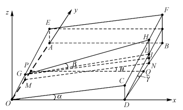
FIG. 3 Spatial relationship between measurement axis of inclination sensor and orbit state
In FIG. 3, the X-axis, Y-axis and Z-axis are the transverse, longitudinal and vertical directions of the track respectively; the plane ABDO is the horizontal plane; the plane EFCO is the actual track plane with slope Angle γ and ultra-high Angle α elements; and the line GH is the measurement axis of the inclination sensor. The Angle between the horizontal projection line MN and the lateral side of the track is θ, then ∠ HGI is the ultra-high Angle measurement value β of the track measuring instrument, and the line segment HI is the ultra-high measurement value, but the ultra-high Angle of the track is α, and the corresponding benchmark ultra-high value should be the line segment CD, therefore, due to the installation error Angle θ of the inclination sensor, The resulting ultra-high measurement error Δh of the orbit measuring instrument is

According to the spatial geometric relationship in Figure 2, it can be obtained

Substitute formula (3) into formula (2) and sort it out

Where OC is the distance between the center of the left and right rail.
Select 1 505 mm as the OC reference length, then

Formula (5) refers to the ultra-high measurement error of the orbit measuring instrument caused by the installation error of the inclination sensor.
TB 10621-2014 « High-speed Railway Design Code »[12] stipulates that the maximum slope of the line should not be greater than 20‰, the maximum ultra-high design value is 175 mm, then the corresponding slope Angle γ is 0 ~ 1.15°, and the ultra-high Angle α is 0 ~ 6.68°. It can be seen from formula (5), The ultra-high measurement error Δh and ultra-high Angle α are cosine function relations, and ultra-high Angle α is very small, and its cosine value has little influence on ultra-high measurement error Δh, which can be ignored. Then equation (5) can be simplified as

For the installation error Angle θ and slope Angle γ in equation (6), different values are taken within their value ranges, and the calculated ultra-high measurement error is shown in Table 1.

Table 1 Ultra-high measurement error (unit mm)
As can be seen from Table 1, even though the installation error Angle θ of the inclination sensor is very small, it still has a serious impact on the ultra-high measurement of the track measuring instrument in the line slope section, and the error value even exceeds 1 mm, which directly causes a misjudgment of the actual ultra-high level of the track. In order to meet the specification requirements that the error of the ultra-high measurement indication value of the track measuring instrument at any position of the line is not more than ± 0.30mm, the installation error Angle θ of the inclination sensor should not be greater than 0 5°.
4 Conclusion
1) Affected by the installation error, the double axis of the inclination sensor is not parallel to the horizontal and longitudinal of the orbit measuring instrument, and there is a certain Angle, which causes the ultra-high measurement error of the orbit measuring instrument.
2) Different installation errors of the inclination sensor will have different impacts on the ultra-high measurement of the track measuring instrument. When one axis of the inclination sensor is parallel to the horizontal or vertical of the track measuring instrument, and the other axis is not parallel, it has no impact on the ultra-high measurement or can be compensated by calibration; when the two axes of the inclination sensor are not parallel to the horizontal or vertical of the track measuring instrument, it can be corrected by calibration. Its influence on ultra-high measurement will change with the change of orbit geometry, and can not be compensated by calibration.
3) The installation error of the inclination sensor has different effects on the ultra-high measurement of the track measuring instrument in different line states. When the line does not exist or there is only ultra-high, its impact on ultra-high measurement is small and negligible; when the line has slope, its impact on ultra-high measurement is serious, especially when the line has both ultra-high and slope, more attention should be paid to the check of ultra-high measurement.
4) In order to meet the specification requirements that the ultra-high measurement error of the track measuring instrument at any position of the line is not more than ±0 30 mm ꎬ the installation error Angle of the inclination sensor should not be greater than 0.5°.
Reference
[1] AN Guodong. Research and Application of precision Engineering measurement Technical standards for high-speed railway [J]. Journal of Railways 2010 32(2):98 ~ 104.
[2] DU Xiguang. Research on static Detection Method of ballastless high-speed rail Track [D]. Fuxin: Liaoning Technical University, 2015.
[3] LIU Lei. Research on ultra-high curve of 400 km/h high-speed railway [J]. Railway Construction 2017 57(4):91 ~ 94 101.
[4] Ministry of Railways of the People's Republic of China. Specification for Engineering Survey of high-speed railway: TB10601-2009 [S]. Beijing: China Railway Press 2009.
[5] Ministry of Railways of the People's Republic of China. Railway track Inspection Instrument :TB/T 3147-2012 [S]. Beijing: China Railway Press, 2012.
[6] WANG Kun. Research on Key technology of error control of high-speed rail track inspection instrument [D]. Nanchang: Nanchang University 2014.
[7] DENG Chuan. Analysis of Ultra-High Measurement of track Measuring Instrument [J]. Railway Construction 2015 55(12):127 ~ 129.
[8] YU Zhaoxu. Application and Discussion of Key Technologies of Ballastless Track Construction Survey [D]. Fuxin: Liaoning Technical University, 2013.
[9] PENG Chunxiu. Influence of track Slope on measuring static superelevation [J]. Railway Technical Supervision 2014(3):17 ~ 19.
[10] Wang Zhongnan. Research on Key Problems in Main static parameter measurement technology of railway track [D]. Harbin: Harbin Institute of Technology 2009.
[11] Jia Peigang ꎬ Zhang Ming. Calibration of Biaxial tilt Sensor for Vehicle body [J]. Journal of Xi 'an Technological University 2012 32(12):1000 ~ 1003.
[12] National Railway Administration. Design Specification for high-speed railway :TB 10621-2014 [S]. Beijing: China Railway Press 2015